1
\$\begingroup\$

I have some Hall effect flowmeters that pulse their input voltage on their signal line appear to work more accurately at the top end of their input voltage range (5-12 V). The problem is my controller is a Raspberry Pi with 3.3 V GPIOs which reportedly will fry with a 12 V input.

I am a novice with electronics. It appears that a voltage divider would work if I can find an appropriate pair of resistors; 3.3 V from 12 V is the target, but I believe the Raspberry Pi will perceive anything above 2.2 V to be "High" and register the pulse. My main problem is finding room on my project board for four pairs of resistors.

Is a voltage divider "the" way to do this (reduce a potential 12 V PWM down to a 3.3 V PWM signal) or is there a better way?

EDIT - Data sheet - I cannot find such a thing, however, the flowmeters are made by Gredia, they have many models, varying in size; I have three different models, 201, 301, 402B, here is one I bought from Amazon: https://www.amazon.com/gp/product/B07MY7H45V/ref=ppx_yo_dt_b_search_asin_title?ie=UTF8&th=1. I did not receive any data sheet with any of the meters I bought, other than what the three conductors are, and the Amazon page had better detail.

Sorry I'm not much help, when I power these with 3.3 V, I can read the pulses on a GPIO, using Raspberry Pi's "pull down" argument.

\$\endgroup\$
6
  • 2
    \$\begingroup\$ Welcome! Eight 0402 resistors take 4 mm^2 of PCB area, plus routing. Are you that low on space? \$\endgroup\$
    – winny
    Commented Apr 13, 2023 at 11:02
  • \$\begingroup\$ There likely is a better way, but it depends on PWM frequency and output drive type and output drive current of the sensor. Resistive divider is usually bad for fast signals like PWM \$\endgroup\$
    – Justme
    Commented Apr 13, 2023 at 11:02
  • \$\begingroup\$ If you could post a pic of the board we can probably present a good way to patch in 4 resistors. \$\endgroup\$
    – Lundin
    Commented Apr 13, 2023 at 12:33
  • \$\begingroup\$ @Justme - The PWM frequency has never been more than 100 Hz on any of the devices. \$\endgroup\$ Commented Apr 13, 2023 at 19:34
  • \$\begingroup\$ @winny - I'm at the prototyping stage, using thin film linear resistors. \$\endgroup\$ Commented Apr 13, 2023 at 19:39

3 Answers 3

2
\$\begingroup\$

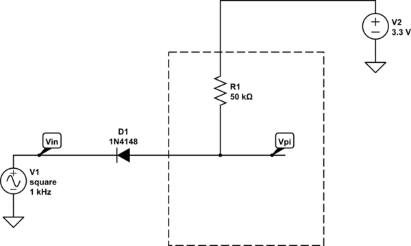
The lowest parts count (assuming a push-pull output) would be to use a diode and the internal pullup in the Pi. The 12V supply and Pi supply need to have a common ground.

schematic

simulate this circuit – Schematic created using CircuitLab

If the Hall pickup has an open collector NPN you don't even need the diode. A datasheet should clear up what is going on there, and I'll revise if you supply one edited into the original question. If you connect a push-pull output without the diode you'll kill the Pi quite expeditiously.

However, personally, I would not do that. It has bad noise immunity (the internal pullup is pretty high resistance, among other issues) and if D1 is inserted the wrong way or shorted the Pi is toast.

In particular if your sensors are off the board and some distance away I'd consider using galvanic isolation (eg. opto-isolators or other kinds of isolators) , which will keep the 12V entirely away from the Pi and will prevent noise picked up by the wiring from disrupting the Pi.

If the EMI environment is very benign (no relays, short wires, etc.) then a simple voltage divider (turn off the internal pullup on the GPIO pin) would be a decent compromise.

\$\endgroup\$
2
  • 1
    \$\begingroup\$ opto-isolators - I think that might be the ticket, $7 for a four channel isolator \$\endgroup\$ Commented Apr 13, 2023 at 21:19
  • 1
    \$\begingroup\$ I did buy some opto-isolators and they work perfectly. If I ever create a PCB for this, I'll add the opto-isolator chips. Thanks \$\endgroup\$ Commented Apr 17, 2023 at 21:39
3
\$\begingroup\$

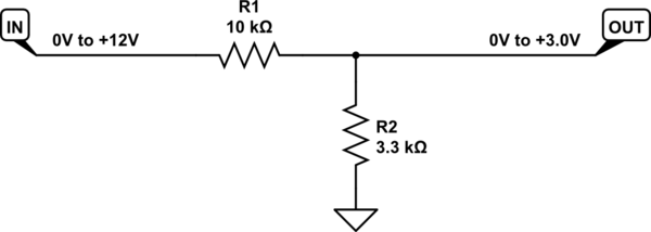
A potential divider is perfectly fine (as long as the sensor ouptut is not open collector, see my last suggestion below):

schematic

simulate this circuit – Schematic created using CircuitLab

The relationship between input and output potentials is:

$$ V_{OUT} = V_{IN} \times \frac{R_2}{R_1+R_2} $$

If there's any chance that the input might stray outside the bounds 0V to 12V, this will also restrict current flowing via the input protection diodes of the GPIO line.

If you wish to power your hall sensors from 5V, you need to increase R2 to compensate. Use the above formula to solve for an appropriate R1, given \$V_{IN}=+5V\$.

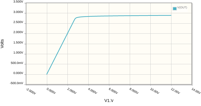
If you can't yet decide whether to power your sensor from a 12V or 5V supply (or anything over 5V for that matter), then you can clamp the signal's potential with a zener diode, to handle almost any maximum input potential:

schematic

simulate this circuit

That gets you this response (Y axis), from an input (X axis) sweeping from 0V to +12V:

enter image description here

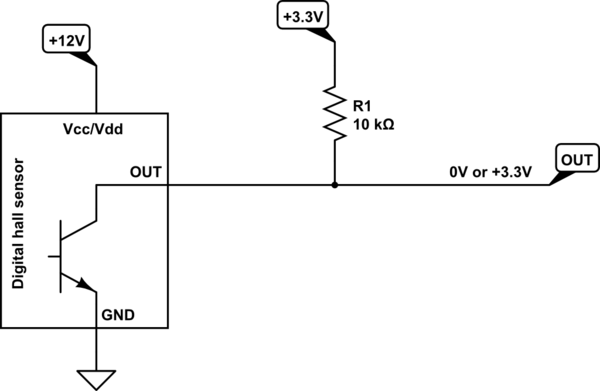
I suspect that your sensor may have an open collector (or open drain) output, in which case, the solution is even simpler:

schematic

simulate this circuit

No protection necessary here, just a single pull-up resistor to +3.3V, but beware that if the sensor output is not open collector, you'll break the GPIO. Check the sensor's datasheet!

\$\endgroup\$
1
\$\begingroup\$

You can do this without a voltage divider as well, either by using a Zener, an LED across the input with a resistor in series with the sensor, or place a Schottky diode from the input to the 3.3 V rail.
Here are examples:

schematic

simulate this circuit – Schematic created using CircuitLab

P.S.: It is not clear what type of output is on your sensor. If it's an NPN open collector, you could simply use a pull-up resistor to the 3.3V rail, as others have indicated in their answers.

\$\endgroup\$
1
  • \$\begingroup\$ If going this route then maybe use a "shunt voltage reference" kind of high precision zener - then the same component type can also be used as the ADC Vref, for better accuracy than the general 3V3 supply. \$\endgroup\$
    – Lundin
    Commented Apr 13, 2023 at 12:41

Your Answer

By clicking “Post Your Answer”, you agree to our terms of service and acknowledge you have read our privacy policy.

Not the answer you're looking for? Browse other questions tagged or ask your own question.