Bounty Ended with 25 reputation awarded by CommunityBot
added 270 characters in body
Source Link
sai
  • 4.4k
  • 1
  • 3
  • 14

Let us take the example of the MOSFET with open drain.

There are 2 cases:

  1. When VGS << VTH, the drain terminal is indeed a high impedance floating node
  2. When VGS >> VTH,, the drain terminal is not a floating node. In this case, there is a low impedance between the drain and source.

enter image description here

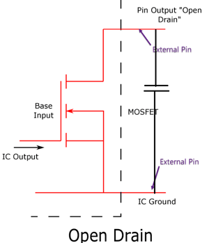
Assume initially VGS << VTH and the drain is sitting at 0V according to your simulation without pullup. Basically, you can visualize this situation as a capacitance across drain-bulk junction as shown which is holding a charge of 5V (drain voltage = 0V and bulk/source voltage = -5V). Subsequently, when VGS >> VTH the drain-source becomes a low impedance and hence discharges the cap fully. Thus, the drain voltage becomes equal to the source voltage i.e. -5V.

Essentially, the pullup resistor is only needed to pull the drain high. To pull the drain low, we just need VGS >> VTH to be satisfied. If there is no pullup in this case, the drain capacitance will get discharged and eventually drain voltage = source voltage

When Vgs>Vth, channel inversion happens and hence there is a path available for the current. If there is a path available for current, it is low impedance. Drain to source is hence low impedance but drain to supply is high impedance because it has no path to supply.

Let us take the example of the MOSFET with open drain.

There are 2 cases:

  1. When VGS << VTH, the drain terminal is indeed a high impedance floating node
  2. When VGS >> VTH,, the drain terminal is not a floating node. In this case, there is a low impedance between the drain and source.

enter image description here

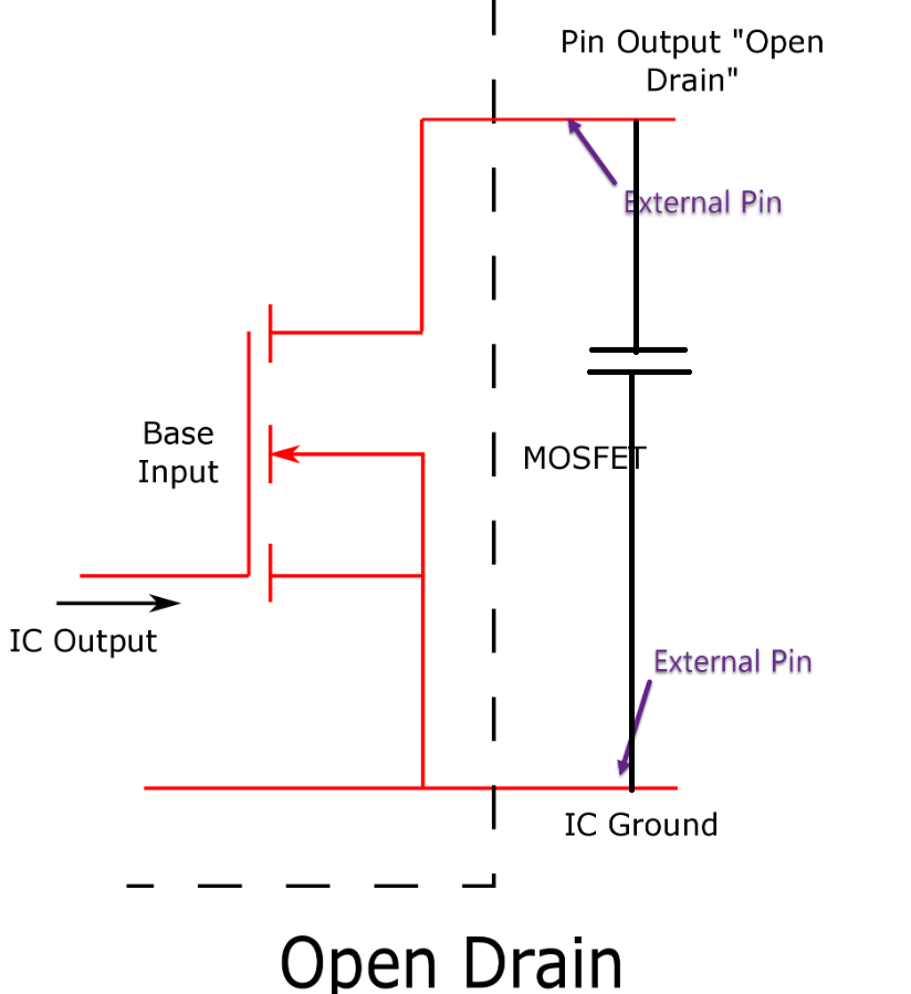
Assume initially VGS << VTH and the drain is sitting at 0V according to your simulation without pullup. Basically, you can visualize this situation as a capacitance across drain-bulk junction as shown which is holding a charge of 5V (drain voltage = 0V and bulk/source voltage = -5V). Subsequently, when VGS >> VTH the drain-source becomes a low impedance and hence discharges the cap fully. Thus, the drain voltage becomes equal to the source voltage i.e. -5V.

Essentially, the pullup resistor is only needed to pull the drain high. To pull the drain low, we just need VGS >> VTH to be satisfied. If there is no pullup in this case, the drain capacitance will get discharged and eventually drain voltage = source voltage

When Vgs>Vth, channel inversion happens and hence there is a path available for the current. If there is a path available for current, it is low impedance. Drain to source is hence low impedance but drain to supply is high impedance because it has no path to supply.
Reduced large images to viewable sizes to avoid lots of scrolling. Removed SHOUTY bold.
Source Link
TonyM
  • 23.8k
  • 4
  • 40
  • 65

Let us take the example of the MOSFET with open drain.

There are 2 cases:

  1. When VGS << VTH, the drain terminal is indeed a high impedance floating node
  2. When VGS >> VTH,, the drain terminal is not a floating node. In this case, there is a low impedance between the drain and source.

enter image description hereenter image description here

Assume initially VGS << VTH and the drain is sitting at 0V according to your simulation without pullup. Basically, you can visualize this situation as a capacitance across drain-bulk junction as shown which is holding a charge of 5V (drain voltage = 0V and bulk/source voltage = -5V). Subsequently, when VGS >> VTH the drain-source becomes a low impedance and hence discharges the cap fully. Thus, the drain voltage becomes equal to the source voltage i.e., -5V.

Essentially, the pullup resistor is only needed to pull the drain high. To pull the drain low, we just need VGS >> VTH to be satisfied. If there is no pullup in this case, the drain capacitance will get discharged and eventually drain voltage = source voltage Essentially, the pullup resistor is only needed to pull the drain high. To pull the drain low, we just need VGS >> VTH to be satisfied. If there is no pullup in this case, the drain capacitance will get discharged and eventually drain voltage = source voltage

Let us take the example of the MOSFET with open drain.

There are 2 cases:

  1. When VGS << VTH, the drain terminal is indeed a high impedance floating node
  2. When VGS >> VTH,, the drain terminal is not a floating node. In this case, there is a low impedance between the drain and source.

enter image description here

Assume initially VGS << VTH and the drain is sitting at 0V according to your simulation without pullup. Basically, you can visualize this situation as a capacitance across drain-bulk junction as shown which is holding a charge of 5V (drain voltage = 0V and bulk/source voltage = -5V). Subsequently, when VGS >> VTH the drain-source becomes a low impedance and hence discharges the cap fully. Thus, the drain voltage becomes equal to the source voltage i.e., -5V.

Essentially, the pullup resistor is only needed to pull the drain high. To pull the drain low, we just need VGS >> VTH to be satisfied. If there is no pullup in this case, the drain capacitance will get discharged and eventually drain voltage = source voltage

Let us take the example of the MOSFET with open drain.

There are 2 cases:

  1. When VGS << VTH, the drain terminal is indeed a high impedance floating node
  2. When VGS >> VTH,, the drain terminal is not a floating node. In this case, there is a low impedance between the drain and source.

enter image description here

Assume initially VGS << VTH and the drain is sitting at 0V according to your simulation without pullup. Basically, you can visualize this situation as a capacitance across drain-bulk junction as shown which is holding a charge of 5V (drain voltage = 0V and bulk/source voltage = -5V). Subsequently, when VGS >> VTH the drain-source becomes a low impedance and hence discharges the cap fully. Thus, the drain voltage becomes equal to the source voltage i.e. -5V.

Essentially, the pullup resistor is only needed to pull the drain high. To pull the drain low, we just need VGS >> VTH to be satisfied. If there is no pullup in this case, the drain capacitance will get discharged and eventually drain voltage = source voltage

Source Link
sai
  • 4.4k
  • 1
  • 3
  • 14

Let us take the example of the MOSFET with open drain.

There are 2 cases:

  1. When VGS << VTH, the drain terminal is indeed a high impedance floating node
  2. When VGS >> VTH,, the drain terminal is not a floating node. In this case, there is a low impedance between the drain and source.

enter image description here

Assume initially VGS << VTH and the drain is sitting at 0V according to your simulation without pullup. Basically, you can visualize this situation as a capacitance across drain-bulk junction as shown which is holding a charge of 5V (drain voltage = 0V and bulk/source voltage = -5V). Subsequently, when VGS >> VTH the drain-source becomes a low impedance and hence discharges the cap fully. Thus, the drain voltage becomes equal to the source voltage i.e., -5V.

Essentially, the pullup resistor is only needed to pull the drain high. To pull the drain low, we just need VGS >> VTH to be satisfied. If there is no pullup in this case, the drain capacitance will get discharged and eventually drain voltage = source voltage