It is so wonderful that there are such "theoretical questions" that make us think and reveal the ideas behind mysterious circuits.
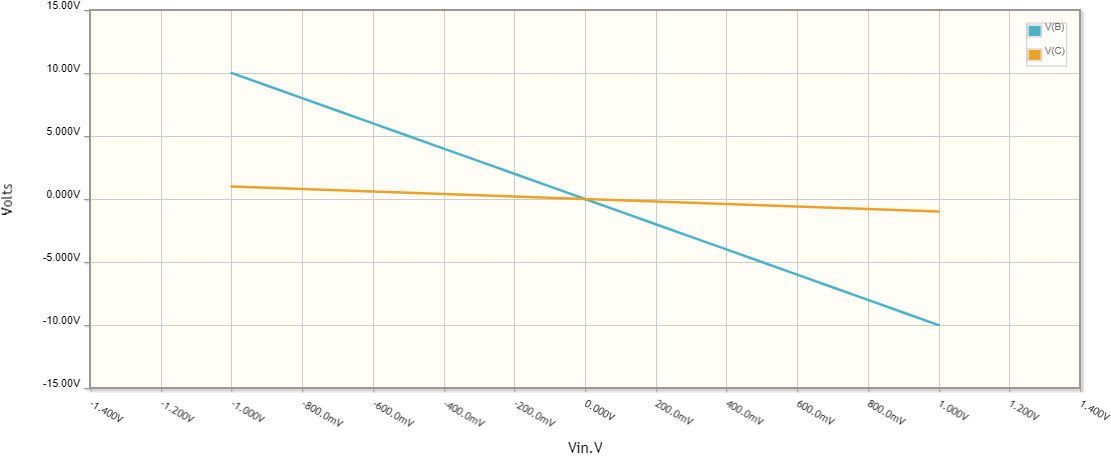
When I read this question, my knee-jerk reaction was that this is impossible. But the problem remained dormant in my head, and at some point I began to make a connection with the somewhat strange circuit of an amplifier with a T-bridge in the negative feedback.
Basic idea
... is extremely simple: According to Ohm's law, the current flowing through a resistor R with applied voltage V across it is I = V/R. If we actually supply the resistor with, for example, ten times lower voltage, the current will also decrease ten times (I = V/10R) and it will appear that the resistance has increased ten times (R = 10V/R).
Of course, there is a "small" catch here (as in any circus trick:-) - we see the voltage V when actually a voltage of V/10 is applied.
Implementation
Ohm's circuit with true 10 k resistance
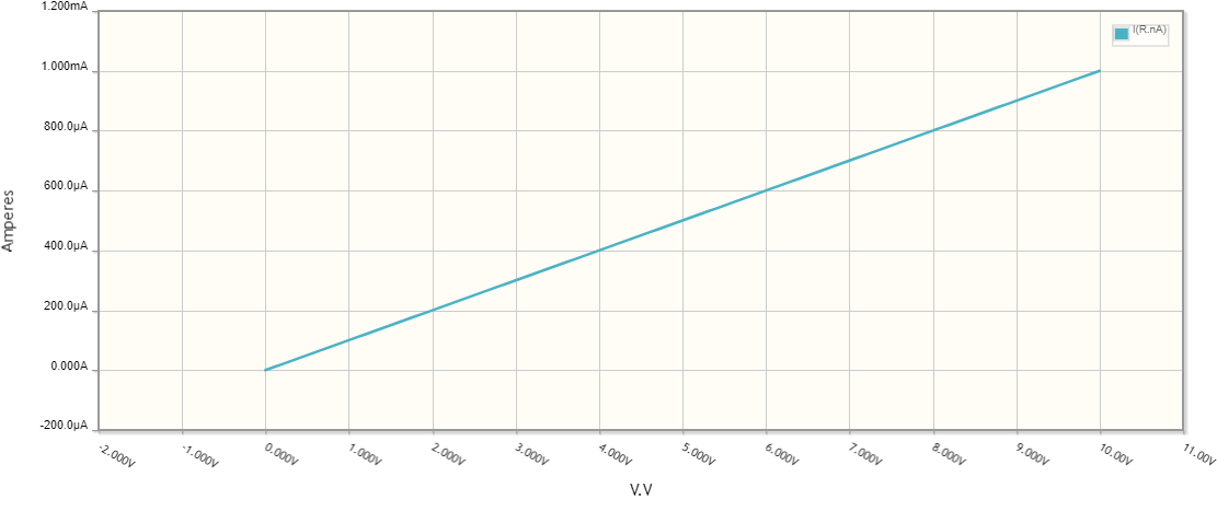
As an example, the current flowing through a 10 k resistor R with applied 10 V voltage V across it is I = 1 mA. We know that the resistance is 10 k but we can also measure the current and calculate the resistance - R = V/R = 10 V/1 mA = 10 k.
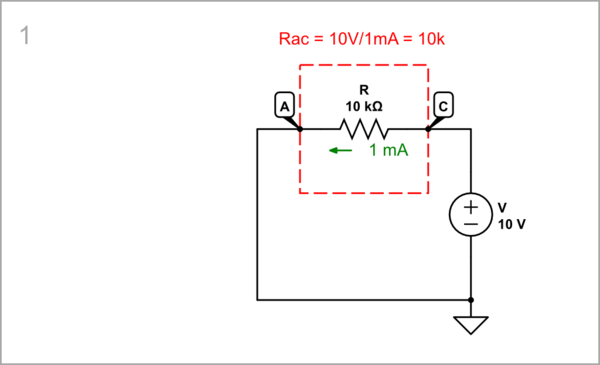
simulate this circuit – Schematic created using CircuitLab
Inverting amplifier with true 10 k R2
As another example, the 10 k resistor R2 and R1 set a gain of -1 of an op-amp inverting amplifier.
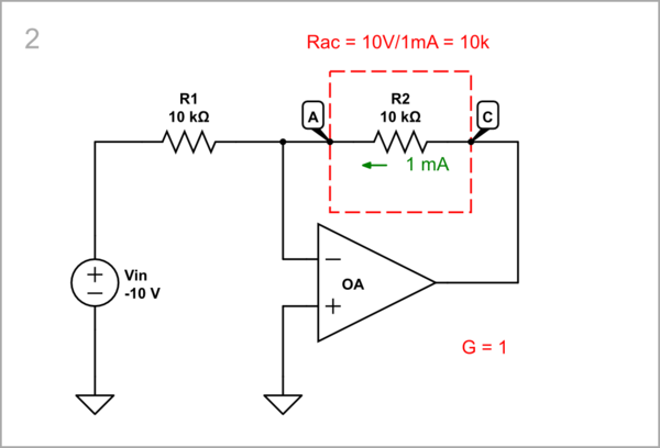
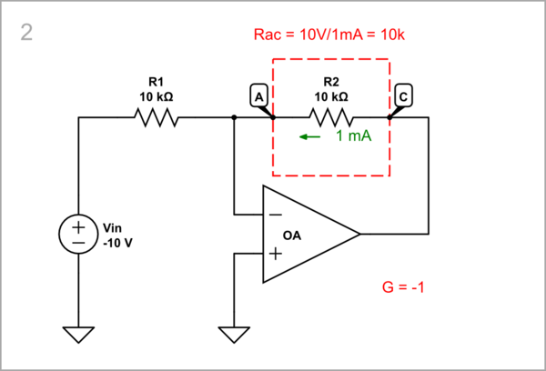
simulate this circuitsimulate this circuit
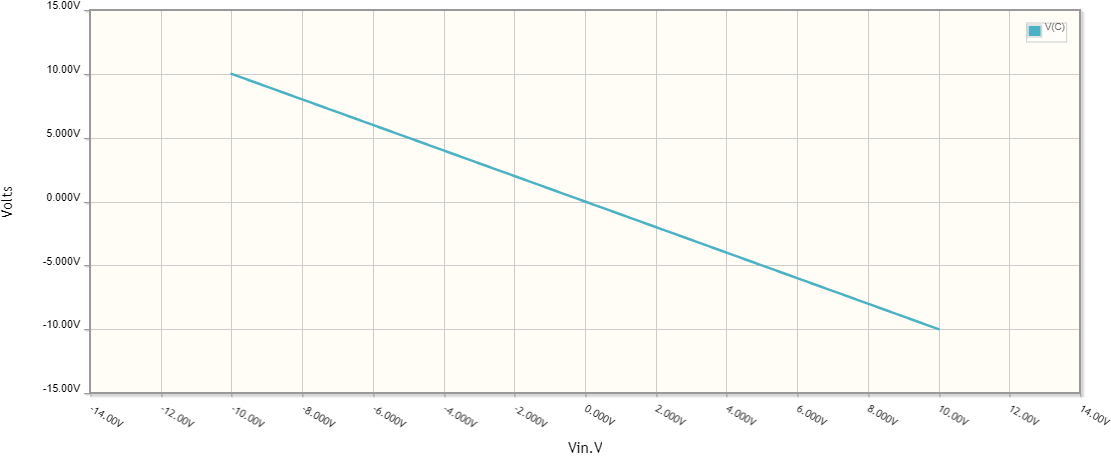
Ohm's circuit with virtual 100 k resistance
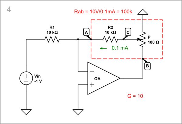
Now let's apply our trick to virtually increase the 10 k resistance up to 100 k. For this purpose, we connect a low-resistance potentiometer P between the voltage source and R2 and adjust its gain equal to 0.1. As a result, the current decreases to 0.1 mA and we see a 100 k resistance.
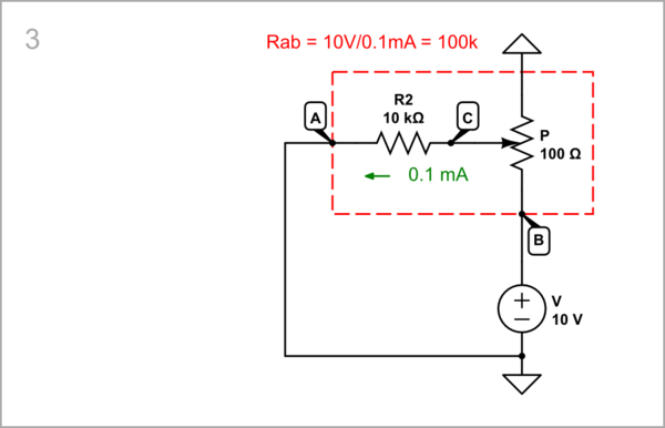
simulate this circuit
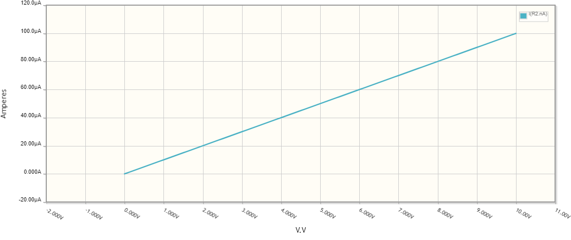
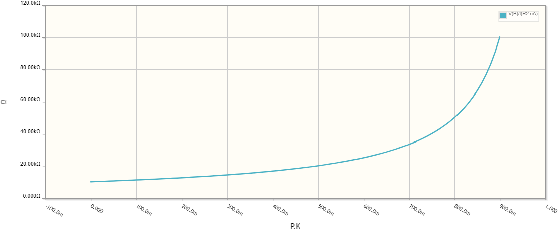
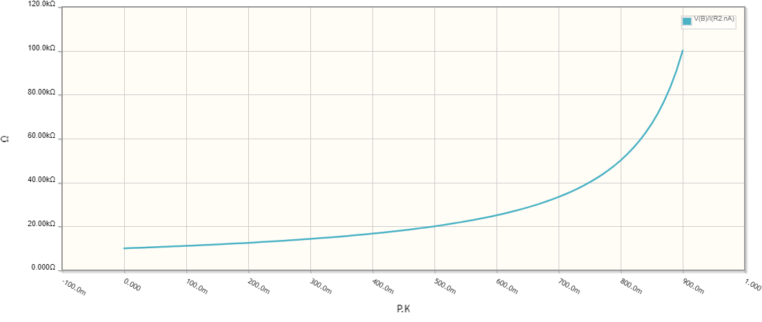
When we sweep the potentiometer's gain from 0 to 0.9, we see that the "R2" resistance changes from 10 to 100 k but this is actually the total circuit resistance between nodes A and B. In this way, we can say that the P original resistance range (0 ÷ 100 ohms) is expanded to 10 ÷ 100 kohms.
Inverting amplifier with virtual 100 k R2
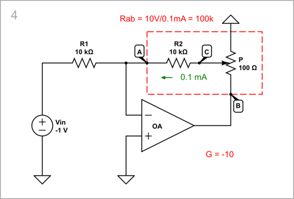
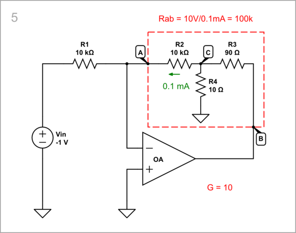
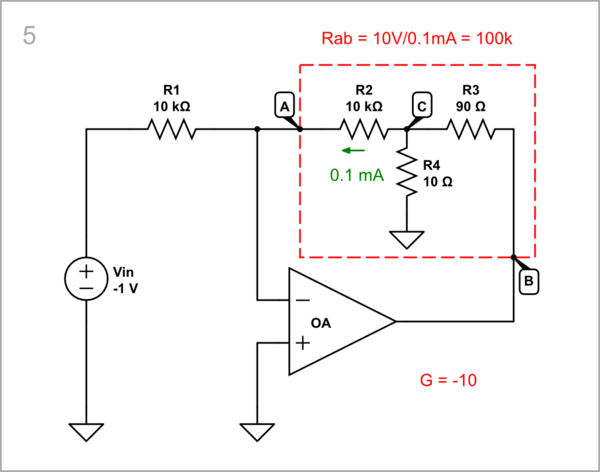
We can see this idea implemented in op-amp amplifiers. For example, the -1 gain of the inverting amplifier above is increased up to -10 by virtually increasing R2 up to 100 k.
simulate this circuitsimulate this circuit
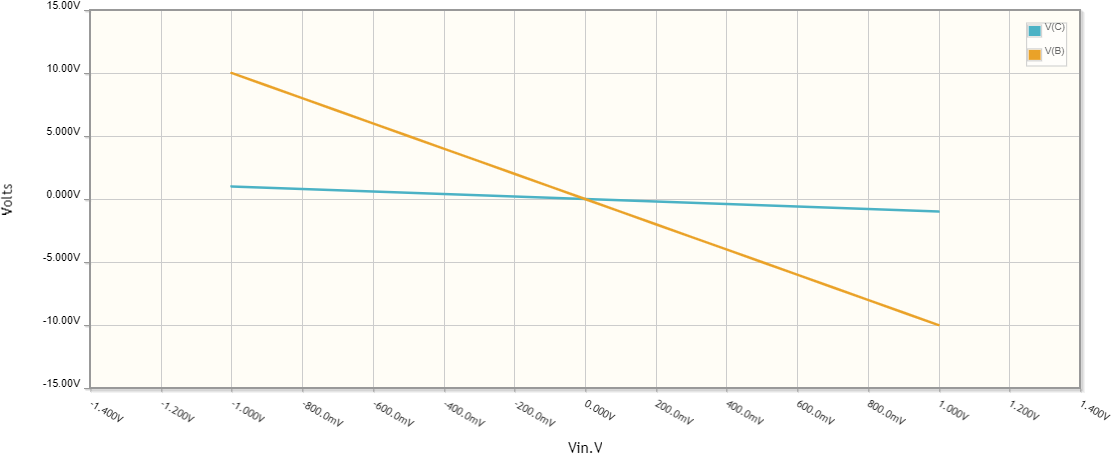
Inverting amplifier with T bridge instead R2
This circuit is usually drawn in a prettier way with the three resistors R2, R3 and R4 grouped together in the shape of the letter "T".
simulate this circuitsimulate this circuit
