added 7 characters in body
Source Link
JRE
  • 73.6k
  • 10
  • 112
  • 195

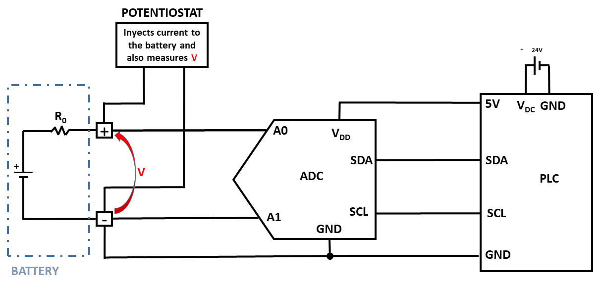
I have designed a circuit to measure the voltage of a battery. This battery is being cycled all the time by a potentiostat (charging-discharging) which inyectsinjects positive current to charge the battery and negative to discharge it (and simultaneously it measures the battery voltage V).) In the past, I had problems with the voltage measurement (low accuracy) and the solution was to add a digital isolator to separate both analog and digital grounds (initial question here).

This is the original design with no isolator:

enter image description here

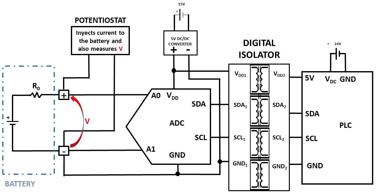
And thisThis is the new design with the digital isolator for I2C communication between the ADC (ADS1115) and the PLC (based inon the Arduino Mega):

enter image description here

My questions are:

  1. I have solved the problem in an very practical way, but how can I prove "visually" (using electrical diagrams like these ones and drawing currents/voltages) or in any scientific way that with the new design the ground loops dissapeared?. I find it very difficult to imagine this as normally the ground loops are not drawn.

    I have solved the problem in an very practical way, but how can I prove "visually" (using electrical diagrams like these ones and drawing currents/voltages) or in any scientific way that with the new design the ground loops disappeared? I find it very difficult to imagine this as normally the ground loops are not drawn.
  2. I had to use a DC DC to power the ADC, because if I use the 5V coming from the PLC though the isolator, I would get no I2C communication. Why is this?

    I had to use a DC/DC converter to power the ADC, because if I use the 5V coming from the PLC though the isolator, I would get no I2C communication. Why is this?
I have designed a circuit to measure the voltage of a battery. This battery is being cycled all the time by a potentiostat (charging-discharging) which inyects positive current to charge the battery and negative to discharge it (and simultaneously it measures the battery voltage V). In the past I had problems with the voltage measurement (low accuracy) and the solution was to add a digital isolator to separate both analog and digital grounds (initial question here).

This is the original design with no isolator:

enter image description here

And this is the new design with the digital isolator for I2C communication between the ADC (ADS1115) and the PLC (based in Arduino Mega):

enter image description here

My questions are:

  1. I have solved the problem in an very practical way, but how can I prove "visually" (using electrical diagrams like these ones and drawing currents/voltages) or in any scientific way that with the new design the ground loops dissapeared?. I find it very difficult to imagine this as normally the ground loops are not drawn.

  2. I had to use a DC DC to power the ADC, because if I use the 5V coming from the PLC though the isolator, I would get no I2C communication. Why is this?

I have designed a circuit to measure the voltage of a battery. This battery is being cycled all the time by a potentiostat (charging-discharging) which injects positive current to charge the battery and negative to discharge it (and simultaneously it measures the battery voltage V.) In the past, I had problems with the voltage measurement (low accuracy) and the solution was to add a digital isolator to separate both analog and digital grounds (initial question here).

This is the original design with no isolator:

enter image description here

This is the new design with the digital isolator for I2C communication between the ADC (ADS1115) and the PLC (based on the Arduino Mega):

enter image description here

My questions are:

  1. I have solved the problem in an very practical way, but how can I prove "visually" (using electrical diagrams like these ones and drawing currents/voltages) or in any scientific way that with the new design the ground loops disappeared? I find it very difficult to imagine this as normally the ground loops are not drawn.
  2. I had to use a DC/DC converter to power the ADC, because if I use the 5V coming from the PLC though the isolator, I would get no I2C communication. Why is this?
added 154 characters in body
Source Link
bardulia
  • 407
  • 4
  • 10

Isolating Understanding ADC measurementdigital isolation to avoid ground loops

I have designed a circuit to measure the voltage of a battery. This battery is being cycled all the time by a potentiostat (charging-discharging) which inyects positive current to charge the battery and negative to discharge it (and simultaneously it measures the battery voltage V). In the past I had problems with the voltage measurement (low accuracy) and the solution was to add a digital isolator to separate both analog and digital grounds (initial question here).

This is the original design with no isolator:

enter image description here

And this is the new design with the digital isolator for I2C communication between the ADC (ADS1115) and the PLC (based in Arduino Mega):

enter image description here

My question now is: I have solved the problem in an very practical way, but how can I prove "visually" (using electrical diagrams like these ones and drawing currents/voltages) or in any scientific way that with the new design the ground loops dissapeared?. I find it very difficult to imagine this as normally the ground loopsquestions are not drawn.

Edit: a other question: I had to use a DC DC converter for the analog power side, because if not used, I would get no I2c communication. Why is this?

  1. I have solved the problem in an very practical way, but how can I prove "visually" (using electrical diagrams like these ones and drawing currents/voltages) or in any scientific way that with the new design the ground loops dissapeared?. I find it very difficult to imagine this as normally the ground loops are not drawn.

  2. I had to use a DC DC to power the ADC, because if I use the 5V coming from the PLC though the isolator, I would get no I2C communication. Why is this?

Isolating ADC measurement to avoid ground loops

I have designed a circuit to measure the voltage of a battery. This battery is being cycled all the time by a potentiostat (charging-discharging) which inyects positive current to charge the battery and negative to discharge it (and simultaneously it measures the battery voltage V). In the past I had problems with the voltage measurement (low accuracy) and the solution was to add a digital isolator to separate both analog and digital grounds (initial question here).

This is the original design with no isolator:

enter image description here

And this is the new design with the digital isolator for I2C communication between the ADC (ADS1115) and the PLC (based in Arduino Mega):

enter image description here

My question now is: I have solved the problem in an very practical way, but how can I prove "visually" (using electrical diagrams like these ones and drawing currents/voltages) or in any scientific way that with the new design the ground loops dissapeared?. I find it very difficult to imagine this as normally the ground loops are not drawn.

Edit: a other question: I had to use a DC DC converter for the analog power side, because if not used, I would get no I2c communication. Why is this?

Understanding ADC digital isolation to avoid ground loops

I have designed a circuit to measure the voltage of a battery. This battery is being cycled all the time by a potentiostat (charging-discharging) which inyects positive current to charge the battery and negative to discharge it (and simultaneously it measures the battery voltage V). In the past I had problems with the voltage measurement (low accuracy) and the solution was to add a digital isolator to separate both analog and digital grounds (initial question here).

This is the original design with no isolator:

enter image description here

And this is the new design with the digital isolator for I2C communication between the ADC (ADS1115) and the PLC (based in Arduino Mega):

enter image description here

My questions are:

  1. I have solved the problem in an very practical way, but how can I prove "visually" (using electrical diagrams like these ones and drawing currents/voltages) or in any scientific way that with the new design the ground loops dissapeared?. I find it very difficult to imagine this as normally the ground loops are not drawn.

  2. I had to use a DC DC to power the ADC, because if I use the 5V coming from the PLC though the isolator, I would get no I2C communication. Why is this?

added 154 characters in body
Source Link
bardulia
  • 407
  • 4
  • 10

I have designed a circuit to measure the voltage of a battery. This battery is being cycled all the time by a potentiostat (charging-discharging) which inyects positive current to charge the battery and negative to discharge it (and simultaneously it measures the battery voltage V). In the past I had problems with the voltage measurement (low accuracy) and the solution was to add a digital isolator to separate both analog and digital grounds (initial question here).

This is the original design with no isolator:

enter image description here

And this is the new design with the digital isolator for I2C communication between the ADC (ADS1115) and the PLC (based in Arduino Mega):

enter image description here

My question now is: I have solved the problem in an very practical way, but how can I prove "visually" (using electrical diagrams like these ones and drawing currents/voltages) or in any scientific way that with the new design the ground loops dissapeared?. I find it very difficult to imagine this as normally the ground loops are not drawn.

Edit: a other question: I had to use a DC DC converter for the analog power side, because if not used, I would get no I2c communication. Why is this?

I have designed a circuit to measure the voltage of a battery. This battery is being cycled all the time by a potentiostat (charging-discharging) which inyects positive current to charge the battery and negative to discharge it (and simultaneously it measures the battery voltage V). In the past I had problems with the voltage measurement (low accuracy) and the solution was to add a digital isolator to separate both analog and digital grounds (initial question here).

This is the original design with no isolator:

enter image description here

And this is the new design with the digital isolator for I2C communication between the ADC (ADS1115) and the PLC (based in Arduino Mega):

enter image description here

My question now is: I have solved the problem in an very practical way, but how can I prove "visually" (using electrical diagrams like these ones and drawing currents/voltages) or in any scientific way that with the new design the ground loops dissapeared?. I find it very difficult to imagine this as normally the ground loops are not drawn.

Edit: a other question: I had to use a DC DC converter for the analog power side, because if not used, I would get no I2c communication. Why is this?

added 3 characters in body
Source Link
bardulia
  • 407
  • 4
  • 10
Loading
edited title
Source Link
bardulia
  • 407
  • 4
  • 10
Loading
added 53 characters in body
Source Link
bardulia
  • 407
  • 4
  • 10
Loading
Source Link
bardulia
  • 407
  • 4
  • 10
Loading