1
\$\begingroup\$

I have designed a circuit to measure the voltage of a battery. This battery is being cycled all the time by a potentiostat (charging-discharging) which injects positive current to charge the battery and negative to discharge it (and simultaneously it measures the battery voltage V.) In the past, I had problems with the voltage measurement (low accuracy) and the solution was to add a digital isolator to separate both analog and digital grounds (initial question here).

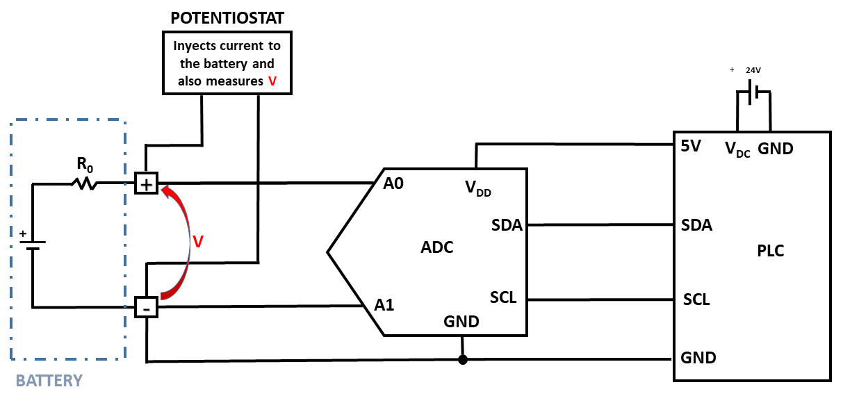
This is the original design with no isolator:

enter image description here

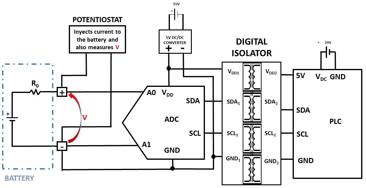
This is the new design with the digital isolator for I2C communication between the ADC (ADS1115) and the PLC (based on the Arduino Mega):

enter image description here

My questions are:

  1. I have solved the problem in an very practical way, but how can I prove "visually" (using electrical diagrams like these ones and drawing currents/voltages) or in any scientific way that with the new design the ground loops disappeared? I find it very difficult to imagine this as normally the ground loops are not drawn.
  2. I had to use a DC/DC converter to power the ADC, because if I use the 5V coming from the PLC though the isolator, I would get no I2C communication. Why is this?
\$\endgroup\$
6
  • 2
    \$\begingroup\$ Did someone actually recommend running the 5V and GND connections through a digital isolator? \$\endgroup\$
    – Nedd
    Commented Nov 15, 2023 at 23:32
  • \$\begingroup\$ @Nedd Jens recommended in one of the comments of one answer to use a adum1250. As it has 4 terminales, I have used all of them so I can isolate also the grounds and the power. What are your thougths about this? \$\endgroup\$
    – bardulia
    Commented Nov 16, 2023 at 11:15
  • 1
    \$\begingroup\$ how do you know that the "low accuracy" problem with the original was caused by a ground loop? And is the battery you are measuring floating or connected to some other equipment? and what about the other 15/24V supply to your measurement circuit? are they isolated? can you post a complete schematic, showing all ground paths? \$\endgroup\$
    – danmcb
    Commented Nov 16, 2023 at 11:59
  • \$\begingroup\$ @danmcb I had only a suspicion, because it also resolved when I disconnected the ground from A1 (negative), however this ADC requires that connection to measure correctly the voltage. Regarding the battery, it is only connected to the potentiostat stated in the diagram. The 15 and 24V supplies are both isolated as they are independent (one is a MURR Eco Rail and the other is a laboratory power supply). Finally, regarding all the ground paths, I will update the schematic with them in the next days. \$\endgroup\$
    – bardulia
    Commented Nov 16, 2023 at 13:16
  • 1
    \$\begingroup\$ OK. Normally a ground loop causing inaccuracy would be because there is mains hum on the signal you are trying to measure. and if that is really the case you should be able to see it wit a scope. Also if you are measuring a slow signal like battery voltage, you should be able to improve that somewhat by low pass filtering in either analogue or digital domain - which doesn't fix your root cause, but offers you some improvement with much less hassle, and will also confirm that the problem really is that without revising all your hardware. \$\endgroup\$
    – danmcb
    Commented Nov 16, 2023 at 13:42

1 Answer 1

2
\$\begingroup\$

You have to use a separate power supply for each side of the ADuM1250 because the ADuM1250 does not pass the power connections through. It isolates the two sides entirely - that's its job. If it passed the power and ground connections through, then it wouldn't be isolated.

That's also the reason why it breaks the ground loop. Ground isn't passed through, so nothing that happens to ground on one side can affect the ground on the other side.

The ADuM1250 passes only the data. It isolates the two circuits so that voltage differences between the two circuits don't cause current to flow between the two circuits. That's what breaks your ground loop.


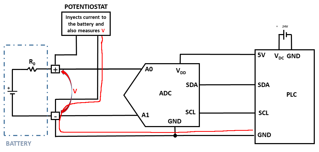
The problem you had was this:

enter image description here

The grounds are different, but are connected together. That causes current to flow between the ground of the potentiostat and the ground of the PLC. That causes the ground wire between the potentiostat, the PLC, and the ADC to be at different voltages at different points along the wire. Every change in current from the potentiostat changes that voltage differential, which makes your ADC readings jump.

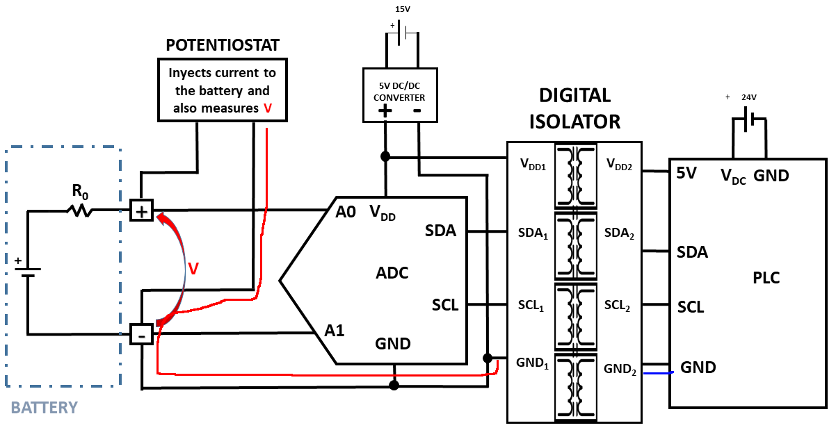
Using the ADuM1250 breaks the flow of current between the two different grounds:

enter image description here

The ADC still shares a ground with the potentiostat (red line,) but since the ADC is powered by an isolated power supply there's no current flow through different grounds - the 0 V for the ADC and the potentiostat are the same.

The PLC ground (blue line) only goes as far as the isolated side of the ADuM1250. No current flows through from the PLC ground to the potentiostat ground.

That's the thing that breaks the loop - there is no path through the ADuM1250 for the ground current.

Vdd1 and GND1 belong to a power supply that is separate from the one connected to Vdd2 and GND2.

\$\endgroup\$
1
  • \$\begingroup\$ That makes sense, thanks a lot! I really like the words you use to describe it. I will give it another thought and come back if needed. \$\endgroup\$
    – bardulia
    Commented Nov 16, 2023 at 13:22

Your Answer

By clicking “Post Your Answer”, you agree to our terms of service and acknowledge you have read our privacy policy.

Not the answer you're looking for? Browse other questions tagged or ask your own question.