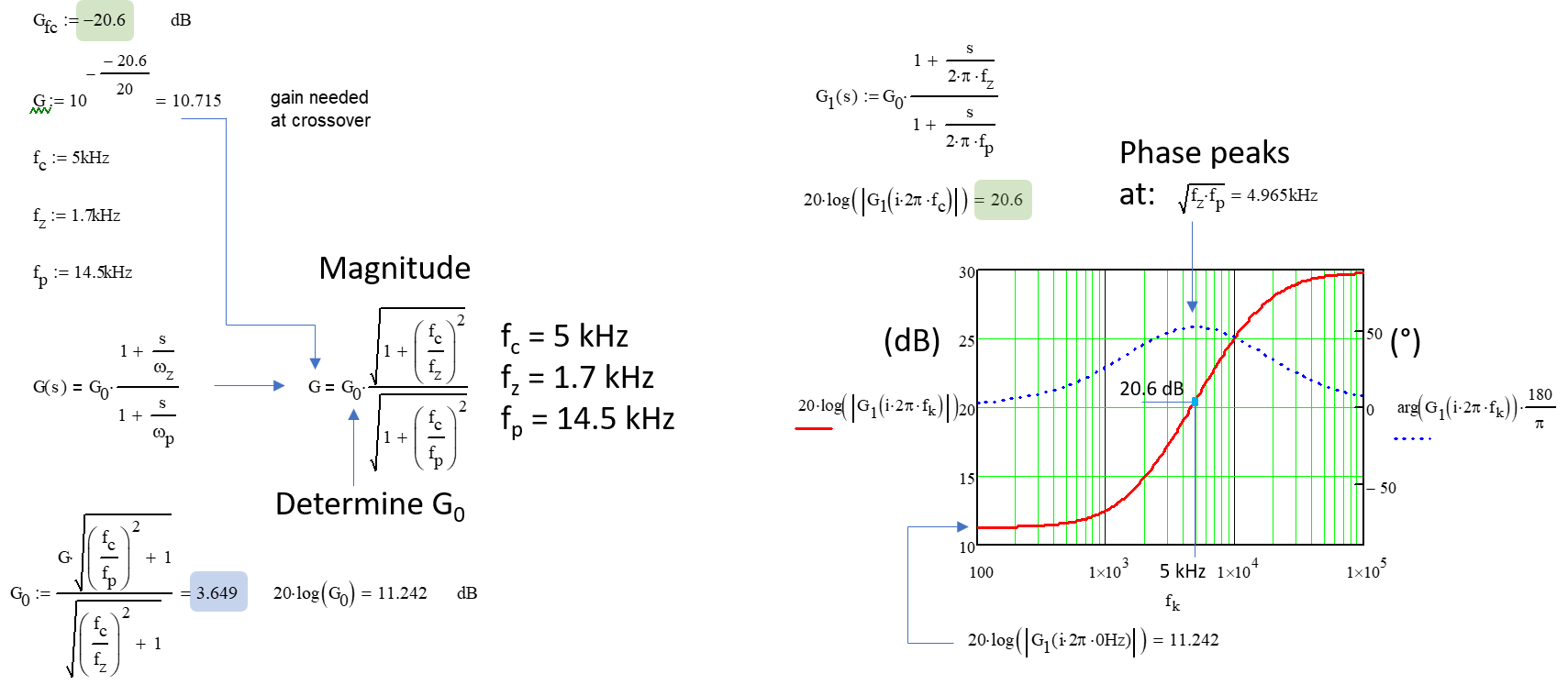
You need to design your active filter - the compensator - so that it exhibits a gain of 20.6 dB at 5 kHz. Calculate the magnitude of the filter with the selected pole-zero pair. This pair is positioned to meet the targeted phase boost:
\$|G(f_c)|=G_0\frac{\sqrt{1+(\frac{f_c}{f_z})^2}}{\sqrt{1+(\frac{f_c}{f_p})^2}}\$.
You know that this magnitude should compensate for the 20.6-dB attenuation at 5 kHz. KnowinKnowing the pole and zero selected for boosting the phase by 52°, what should \$G_0\$ be so that \$|G(5\;\mathrm{kHz)}|=20.6\;\mathrm{dB}\$:
You can also have a look at my free 90+ ready-made templates running on the demo of SIMPLIS for most of them. There are plenty of converters with an automated compensation procedure and the buck in VM and CM is there.
The expression used by Pr. Erickson in the 2nd picture, considers the high-frequency response asymptotes of the power stage \$H\$ and the compensator \$G\$. We know that the loop gain magnitude \$|T|\$ must be equal to one (or 0 dB) at the selected crossover frequency \$f_c=5\;\mathrm{kHz}\$.
The power stage transfer function is \$H(s)=H_0\frac{1}{1+\frac{s}{Q\omega_0}+(\frac{s}{\omega_0})^2}\$. If you consider that the crossover frequency is after the resonance \$f_0\$ - which is the case for proper compensation of a VM buck converter - then, you can write \$H(s)\approx H_0\frac{1}{(\frac{s}{\omega_0})^2}\$. In magnitude, you thus have \$|H(f_c)| \approx H_0(\frac{f_0}{f_c})^2\$.
Same goes with the compensator: \$|G(f_c)|\approx G_0\frac{\sqrt{(\frac{f_c}{f_z})^2}}{\sqrt{(\frac{f_c}{f_p})^2}}\approx G_0 \sqrt{\frac{f_p}{f_z}}\$. Now, if you write the complete loop gain magnitude observed at crossover, you have: \$(\frac{f_0}{f_c})^2H_0\sqrt{\frac{f_p}{f_z}}G_0=1\$. Solving for \$G_0\$ which is the dc gain of the compensator, you have \$G_0=(\frac{f_c}{f_0})^2\frac{1}{H_0}\sqrt{\frac{f_z}{f_p}}=3.67\$.


