Specifying
Source Link
Circuit fantasist
  • 19.4k
  • 2
  • 23
  • 70

The problem

When current driven (via a base resistor) the, a BJ transistor is very sensitive and amplifies small leakage currents. The reason for this behaviour is that the resistance of the PN junction is non-linear. In the beginning it is very high, and at a negligible current the voltage across it rises to several hundred millivolts.

The remedy

Therefore, the initial high input resistance must be lowered. This means that the transistor must be controlled by voltage (via a low-resistance voltage divider).

Intuitive explanation

Transistor "microammeter"

The base-emitter junction can be thought as a "sensitive microammeter". For example, if the collector current needed to saturate the transistor is 1 mA and β = 100, it would be "10 μA ammeter" with 70 kΩ internal resistance and about 700mV voltage drop. Then 930 kΩ leakage resistance will be enough to saturate the transistor.

Actually, the two resistances form a high-resistance voltage divider with a gain of Rbe/(Rb + Rbe). It "produces" 700 mV base voltage that is enough to saturate the transistor.
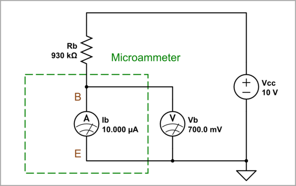
schematic

simulate this circuit – Schematic created using CircuitLab

Transistor "milliammeter"

We can decrease the "microammeter" sensitivity by shunting it e.g. with a 1 kΩ resistor. Then to saturate the transistor, Rb should be onlyless than 13 kΩ.

Now the two resistances Rb and the additional Rbe form a low-resistance voltage divider with the same gain as above. It "produces" 700 mV base voltage that is enough to saturate the transistor.
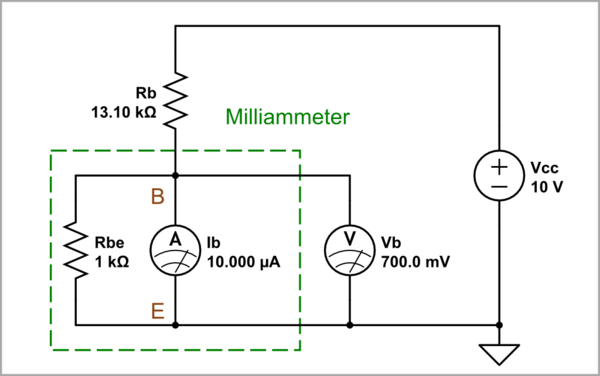
schematic

simulate this circuit

Resistance discriminator

So the last circuit (with a 13 kΩ base resistor and a shunting 1 kΩ resistor between the base and emitter) clearly differentiates the two values ​​of Rb. Assuming it is driven by an open-collector PNP transistor, it means that the first value (> 930 kΩ corresponds to the OFF state of the transistor, and the second (< 13 kΩ) to the ON state.

Conclusion

The role of the shunt resistor R2 connected between the base and the emitter is to decrease the initial high input resistance when Vbe < 700 mV. As a result, the transistor can be controlled only by low base resistance Rb (significant input current), and will not react to small leakage currents.

The problem

When current driven (via a base resistor) the transistor is very sensitive and amplifies small leakage currents. The reason for this behaviour is that the resistance of the PN junction is non-linear. In the beginning it is very high, and at a negligible current the voltage across it rises to several hundred millivolts.

The remedy

Therefore, the transistor must be controlled by voltage (via a low-resistance voltage divider).

Intuitive explanation

Transistor "microammeter"

The base-emitter junction can be thought as a "sensitive microammeter". For example, if the collector current needed to saturate the transistor is 1 mA and β = 100, it would be "10 μA ammeter" with 70 kΩ internal resistance and about 700mV voltage drop. Then 930 kΩ leakage resistance will be enough to saturate the transistor.

Actually, the two resistances form a high-resistance voltage divider with a gain of Rbe/(Rb + Rbe). It "produces" 700 mV base voltage that is enough to saturate the transistor.

schematic

simulate this circuit – Schematic created using CircuitLab

Transistor "milliammeter"

We can decrease the "microammeter" sensitivity by shunting it e.g. with a 1 kΩ resistor. Then to saturate the transistor Rb should be only 13 kΩ.

Now the two resistances Rb and the additional Rbe form a low-resistance voltage divider with the same gain as above. It "produces" 700 mV base voltage that is enough to saturate the transistor.

schematic

simulate this circuit

Resistance discriminator

So the last circuit (with a 13 kΩ base resistor and a shunting 1 kΩ resistor between the base and emitter) clearly differentiates the two values ​​of Rb. Assuming it is driven by an open-collector PNP transistor, it means that the first value (> 930 kΩ corresponds to the OFF state of the transistor, and the second (< 13 kΩ) to the ON state.

The problem

When current driven (via a base resistor), a BJ transistor is very sensitive and amplifies small leakage currents. The reason for this behaviour is that the resistance of the PN junction is non-linear. In the beginning it is very high, and at a negligible current the voltage across it rises to several hundred millivolts.

The remedy

Therefore, the initial high input resistance must be lowered. This means that the transistor must be controlled by voltage (via a low-resistance voltage divider).

Intuitive explanation

Transistor "microammeter"

The base-emitter junction can be thought as a "sensitive microammeter". For example, if the collector current needed to saturate the transistor is 1 mA and β = 100, it would be "10 μA ammeter" with 70 kΩ internal resistance and about 700mV voltage drop. Then 930 kΩ leakage resistance will be enough to saturate the transistor.

Actually, the two resistances form a high-resistance voltage divider with a gain of Rbe/(Rb + Rbe). It "produces" 700 mV base voltage that is enough to saturate the transistor.

schematic

simulate this circuit – Schematic created using CircuitLab

Transistor "milliammeter"

We can decrease the "microammeter" sensitivity by shunting it e.g. with a 1 kΩ resistor. Then to saturate the transistor, Rb should be less than 13 kΩ.

Now the two resistances Rb and the additional Rbe form a low-resistance voltage divider with the same gain as above. It "produces" 700 mV base voltage that is enough to saturate the transistor.

schematic

simulate this circuit

Resistance discriminator

So the last circuit (with a 13 kΩ base resistor and a shunting 1 kΩ resistor between the base and emitter) clearly differentiates the two values ​​of Rb. Assuming it is driven by an open-collector PNP transistor, it means that the first value (> 930 kΩ corresponds to the OFF state of the transistor, and the second (< 13 kΩ) to the ON state.

Conclusion

The role of the shunt resistor R2 connected between the base and the emitter is to decrease the initial high input resistance when Vbe < 700 mV. As a result, the transistor can be controlled only by low base resistance Rb (significant input current), and will not react to small leakage currents.

Minor edit
Source Link
Circuit fantasist
  • 19.4k
  • 2
  • 23
  • 70

The problem

When current driven (via a base resistor) the transistor is very sensitive and amplifies small leakage currents. The reason for this behaviour is that the resistance of the PN junction is non-linear. In the beginning it is very high, and at a negligible current the voltage across it rises to several hundred millivolts.

The remedy

Therefore, the transistor must be controlled by voltage (via a low-resistance voltage divider).

Intuitive explanation

Transistor "microammeter"

The base-emitter junction can be thought as a "sensitive microammeter". For example, if the collector current needed to saturate the transistor is 1 mA and β = 100, it would be "10 μA ammeter" with 70 kΩ internal resistance and about 700mV voltage drop. Then 930 kΩ leakage resistance will be enough to saturate the transistor.

Actually, the two resistances form a high-resistance voltage divider with a gain of Rbe/(Rb + Rbe). It "produces" 700 mV base voltage that is enough to saturate the transistor.

schematic

simulate this circuit – Schematic created using CircuitLab

Transistor "milliammeter"

We can decrease the "microammeter" sensitivity by shunting it e.g. with a 1 kΩ resistor. Then to saturate the transistor Rb should be only 13 kΩ.

Now the two resistances Rb and the additional Rbe form a low-resistance voltage divider with the same gain as above. It "produces" 700 mV base voltage that is enough to saturate the transistor.

schematic

simulate this circuit

Resistance discriminator

So the last circuit (with a 13 kΩ base resistor and a shunting 1 kΩ resistor between the base and emitter) clearly differentiates the two values ​​of Rb. Assuming it is driven by an open-collector PNP transistor, it means that the first value (> 930 kΩ corresponds to the OFF state of the transistor, and the second (< 13 kΩ) to the ON state.

The problem

When current driven (via a base resistor) the transistor is very sensitive and amplifies small leakage currents. The reason for this behaviour is that the resistance of the PN junction is non-linear. In the beginning it is very high, and at a negligible current the voltage across it rises to several hundred millivolts.

The remedy

Therefore, the transistor must be controlled by voltage (via a low-resistance voltage divider).

Intuitive explanation

Transistor "microammeter"

The base-emitter junction can be thought as a "sensitive microammeter". For example, if the collector current needed to saturate the transistor is 1 mA and β = 100, it would be "10 μA ammeter" with 70 kΩ internal resistance. Then 930 kΩ leakage resistance will be enough to saturate the transistor.

Actually, the two resistances form a voltage divider with a gain of Rbe/(Rb + Rbe). It "produces" 700 mV base voltage that is enough to saturate the transistor.

schematic

simulate this circuit – Schematic created using CircuitLab

Transistor "milliammeter"

We can decrease the "microammeter" sensitivity by shunting it e.g. with a 1 kΩ resistor. Then to saturate the transistor Rb should be only 13 kΩ.

schematic

simulate this circuit

The problem

When current driven (via a base resistor) the transistor is very sensitive and amplifies small leakage currents. The reason for this behaviour is that the resistance of the PN junction is non-linear. In the beginning it is very high, and at a negligible current the voltage across it rises to several hundred millivolts.

The remedy

Therefore, the transistor must be controlled by voltage (via a low-resistance voltage divider).

Intuitive explanation

Transistor "microammeter"

The base-emitter junction can be thought as a "sensitive microammeter". For example, if the collector current needed to saturate the transistor is 1 mA and β = 100, it would be "10 μA ammeter" with 70 kΩ internal resistance and about 700mV voltage drop. Then 930 kΩ leakage resistance will be enough to saturate the transistor.

Actually, the two resistances form a high-resistance voltage divider with a gain of Rbe/(Rb + Rbe). It "produces" 700 mV base voltage that is enough to saturate the transistor.

schematic

simulate this circuit – Schematic created using CircuitLab

Transistor "milliammeter"

We can decrease the "microammeter" sensitivity by shunting it e.g. with a 1 kΩ resistor. Then to saturate the transistor Rb should be only 13 kΩ.

Now the two resistances Rb and the additional Rbe form a low-resistance voltage divider with the same gain as above. It "produces" 700 mV base voltage that is enough to saturate the transistor.

schematic

simulate this circuit

Resistance discriminator

So the last circuit (with a 13 kΩ base resistor and a shunting 1 kΩ resistor between the base and emitter) clearly differentiates the two values ​​of Rb. Assuming it is driven by an open-collector PNP transistor, it means that the first value (> 930 kΩ corresponds to the OFF state of the transistor, and the second (< 13 kΩ) to the ON state.

Added another observation
Source Link
Circuit fantasist
  • 19.4k
  • 2
  • 23
  • 70

The problem

When current driven (via a base resistor) the transistor is very sensitive and amplifies small leakage currents. The reason for this behaviour is that the resistance of the PN junction is non-linear. In the beginning it is very high, and at a negligible current the voltage across it rises to several hundred millivolts.

The remedy

Therefore, the transistor must be controlled by voltage (via a low-resistance voltage divider).

Intuitive explanation

Transistor "microammeter"

The base-emitter junction can be thought as a "sensitive microammeter". For example, if the collector current needed to saturate the transistor is 1 mA and β = 100, it would be "10 μA ammeter" with 70 kΩ internal resistance. Then 930 kΩ leakage resistance will be enough to saturate the transistor.

Actually, the two resistances form a voltage divider with a gain of Rbe/(Rb + Rbe). It "produces" 700 mV base voltage that is enough to saturate the transistor.

schematic

simulate this circuit – Schematic created using CircuitLab

Transistor "milliammeter"

We can decrease the "microammeter" sensitivity by shunting it e.g. with a 1 kΩ resistor. Then to saturate the transistor Rb should be only 13 kΩ.

schematic

simulate this circuit

The problem

When current driven (via a base resistor) the transistor is very sensitive and amplifies small leakage currents. The reason for this behaviour is that the resistance of the PN junction is non-linear. In the beginning it is very high, and at a negligible current the voltage across it rises to several hundred millivolts.

The remedy

Therefore, the transistor must be controlled by voltage (via a low-resistance voltage divider).

Intuitive explanation

Transistor "microammeter"

The base-emitter junction can be thought as a "sensitive microammeter". For example, if the collector current needed to saturate the transistor is 1 mA and β = 100, it would be "10 μA ammeter" with 70 kΩ internal resistance. Then 930 kΩ leakage resistance will be enough to saturate the transistor.

schematic

simulate this circuit – Schematic created using CircuitLab

Transistor "milliammeter"

We can decrease the "microammeter" sensitivity by shunting it e.g. with a 1 kΩ resistor. Then to saturate the transistor Rb should be only 13 kΩ.

schematic

simulate this circuit

The problem

When current driven (via a base resistor) the transistor is very sensitive and amplifies small leakage currents. The reason for this behaviour is that the resistance of the PN junction is non-linear. In the beginning it is very high, and at a negligible current the voltage across it rises to several hundred millivolts.

The remedy

Therefore, the transistor must be controlled by voltage (via a low-resistance voltage divider).

Intuitive explanation

Transistor "microammeter"

The base-emitter junction can be thought as a "sensitive microammeter". For example, if the collector current needed to saturate the transistor is 1 mA and β = 100, it would be "10 μA ammeter" with 70 kΩ internal resistance. Then 930 kΩ leakage resistance will be enough to saturate the transistor.

Actually, the two resistances form a voltage divider with a gain of Rbe/(Rb + Rbe). It "produces" 700 mV base voltage that is enough to saturate the transistor.

schematic

simulate this circuit – Schematic created using CircuitLab

Transistor "milliammeter"

We can decrease the "microammeter" sensitivity by shunting it e.g. with a 1 kΩ resistor. Then to saturate the transistor Rb should be only 13 kΩ.

schematic

simulate this circuit

Specifying
Source Link
Circuit fantasist
  • 19.4k
  • 2
  • 23
  • 70
Loading
Source Link
Circuit fantasist
  • 19.4k
  • 2
  • 23
  • 70
Loading