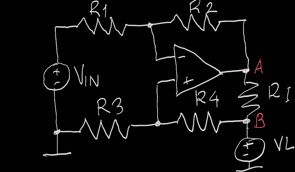
+1 for the inventive spirit and enthusiasm! It is a big challenge to improve such a well-known and already "improved" circuit.
However, in my opinion, the main idea of the circuit is a constant transfer ratio of unity between the points (ends) A and B of the current-setting resistor RI, i.e., R3/(R3 + R4).(R1 + R2)/R1 = 1. This means that when the voltage across load VL varies, the voltage at point A follows the voltage at point B (the so-called "bootstrapping" ), or the difference between them (the voltage drop across RI), respectively, the current through it IR = IL = VRI/RI is constant.
In your specific case, this means that the resistance of resistor R4 must be constant, but it varies when the current range (RI) changes, and the load current should be not constant when the load voltage VL varies.

