added 60 characters in body
Source Link

I've designed a small PCB intended for controlling sensors. This PCB includes an STM32WB55RGV6 MCU, and I created two versions to implement the antenna (one using MIFA and the other a chip antenna). I followed the NUCLEO-WB55RG reference design closely, including all essential components to drive the microcontroller. However, when I try to program the board using the ST-Link V2 with STM32CubeProgrammer, the microcontroller is not detected, and I receive the following error message:

**********************************
16:21:40 : UR connection mode is defined with the HWrst reset mode
16:21:40 : ST-LINK SN  : 52FF71067587575224071767
16:21:40 : ST-LINK FW  : V2J29S7
16:21:40 : Board       : --
16:21:40 : Voltage     : 3.23V
16:21:40 : Error: No STM32 target found! If your product embeds Debug Authentication, 
please perform a discovery using Debug Authentication
***********************************
  • I only use the SWCLK and, SWDIO, Vcc (to the regulator which drives the MCU with 3.3), and GND for programming. Although I also tried to connect the NRST and BOOT pin to see if the problem is because of them, it still does not work. ** disconnecting the crystals didn't help as well.
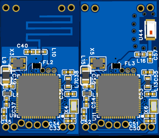
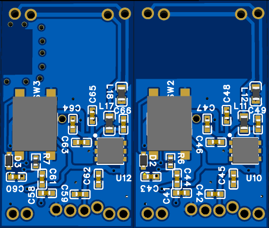
    I have attached both the schematic and PCB layout of my design. I’ve checked the power supply, ground connections, and reset line, and I’m using the correct programming voltage. Does anyone have ideas on what might be causing this issue or steps I might have missed in debugging?

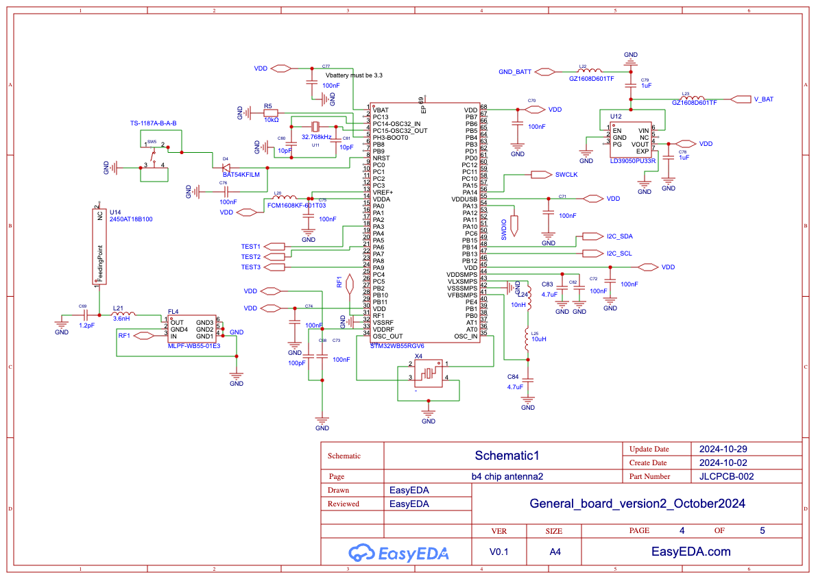
schematic of the designed PCB

front side of the PCB

back side of the PCB

I've designed a small PCB intended for controlling sensors. This PCB includes an STM32WB55RGV6 MCU, and I created two versions to implement the antenna (one using MIFA and the other a chip antenna). I followed the NUCLEO-WB55RG reference design closely, including all essential components to drive the microcontroller. However, when I try to program the board using the ST-Link V2 with STM32CubeProgrammer, the microcontroller is not detected, and I receive the following error message:

**********************************
16:21:40 : UR connection mode is defined with the HWrst reset mode
16:21:40 : ST-LINK SN  : 52FF71067587575224071767
16:21:40 : ST-LINK FW  : V2J29S7
16:21:40 : Board       : --
16:21:40 : Voltage     : 3.23V
16:21:40 : Error: No STM32 target found! If your product embeds Debug Authentication, 
please perform a discovery using Debug Authentication
***********************************
  • I only use the SWCLK and SWDIO for programming. Although I also tried to connect the NRST and BOOT pin to see if the problem is because of them, it still does not work. ** disconnecting the crystals didn't help as well.
    I have attached both the schematic and PCB layout of my design. I’ve checked the power supply, ground connections, and reset line, and I’m using the correct programming voltage. Does anyone have ideas on what might be causing this issue or steps I might have missed in debugging?
schematic of the designed PCB

front side of the PCB

back side of the PCB

I've designed a small PCB intended for controlling sensors. This PCB includes an STM32WB55RGV6 MCU, and I created two versions to implement the antenna (one using MIFA and the other a chip antenna). I followed the NUCLEO-WB55RG reference design closely, including all essential components to drive the microcontroller. However, when I try to program the board using the ST-Link V2 with STM32CubeProgrammer, the microcontroller is not detected, and I receive the following error message:

**********************************
16:21:40 : UR connection mode is defined with the HWrst reset mode
16:21:40 : ST-LINK SN  : 52FF71067587575224071767
16:21:40 : ST-LINK FW  : V2J29S7
16:21:40 : Board       : --
16:21:40 : Voltage     : 3.23V
16:21:40 : Error: No STM32 target found! If your product embeds Debug Authentication, 
please perform a discovery using Debug Authentication
***********************************
  • I only use the SWCLK, SWDIO, Vcc (to the regulator which drives the MCU with 3.3), and GND for programming. Although I also tried to connect the NRST and BOOT pin to see if the problem is because of them, it still does not work. ** disconnecting the crystals didn't help as well.
    I have attached both the schematic and PCB layout of my design. I’ve checked the power supply, ground connections, and reset line, and I’m using the correct programming voltage. Does anyone have ideas on what might be causing this issue or steps I might have missed in debugging?
schematic of the designed PCB

front side of the PCB

back side of the PCB

added 36 characters in body
Source Link
toolic
  • 9.8k
  • 9
  • 27
  • 35

I've designed a small PCB intended for controlling sensors. This PCB includes an STM32WB55RGV6 MCU, and I created two versions to implement the antenna (one using MIFA and the other a chip antenna). I followed the NUCLEO-WB55RG reference design closely, including all essential components to drive the microcontroller. However, when I try to program the board using the ST-Link V2 with STM32CubeProgrammer, the microcontroller is not detected, and I receive the following error message:


16:21:40 : UR connection mode is defined with the HWrst reset mode 16:21:40 : ST-LINK SN : 52FF71067587575224071767 16:21:40 : ST-LINK FW : V2J29S7 16:21:40 : Board : -- 16:21:40 : Voltage : 3.23V 16:21:40 : Error: No STM32 target found! If your product embeds Debug Authentication, please perform a discovery using Debug Authentication


**********************************
16:21:40 : UR connection mode is defined with the HWrst reset mode
16:21:40 : ST-LINK SN  : 52FF71067587575224071767
16:21:40 : ST-LINK FW  : V2J29S7
16:21:40 : Board       : --
16:21:40 : Voltage     : 3.23V
16:21:40 : Error: No STM32 target found! If your product embeds Debug Authentication, 
please perform a discovery using Debug Authentication
***********************************
  • I only use the SWCLK and SWDIO for programming. Although I also tried to connect the NRST and BOOT pin to see if the problem is because of them, it still does not work. ** disconnecting the crystals didn't help as well.
    I have attached both the schematic and PCB layout of my design. I’ve checked the power supply, ground connections, and reset line, and I’m using the correct programming voltage. Does anyone have ideas on what might be causing this issue or steps I might have missed in debugging? Thanks :) schematic of the designed PCB

schematic of the designed PCB

front side of the PCB   

back side of the PCB

I've designed a small PCB intended for controlling sensors. This PCB includes an STM32WB55RGV6 MCU, and I created two versions to implement the antenna (one using MIFA and the other a chip antenna). I followed the NUCLEO-WB55RG reference design closely, including all essential components to drive the microcontroller. However, when I try to program the board using the ST-Link V2 with STM32CubeProgrammer, the microcontroller is not detected, and I receive the following error message:


16:21:40 : UR connection mode is defined with the HWrst reset mode 16:21:40 : ST-LINK SN : 52FF71067587575224071767 16:21:40 : ST-LINK FW : V2J29S7 16:21:40 : Board : -- 16:21:40 : Voltage : 3.23V 16:21:40 : Error: No STM32 target found! If your product embeds Debug Authentication, please perform a discovery using Debug Authentication


  • I only use the SWCLK and SWDIO for programming. Although I also tried to connect the NRST and BOOT pin to see if the problem is because of them, it still does not work. ** disconnecting the crystals didn't help as well.
    I have attached both the schematic and PCB layout of my design. I’ve checked the power supply, ground connections, and reset line, and I’m using the correct programming voltage. Does anyone have ideas on what might be causing this issue or steps I might have missed in debugging? Thanks :) schematic of the designed PCB

front side of the PCB  back side of the PCB

I've designed a small PCB intended for controlling sensors. This PCB includes an STM32WB55RGV6 MCU, and I created two versions to implement the antenna (one using MIFA and the other a chip antenna). I followed the NUCLEO-WB55RG reference design closely, including all essential components to drive the microcontroller. However, when I try to program the board using the ST-Link V2 with STM32CubeProgrammer, the microcontroller is not detected, and I receive the following error message:

**********************************
16:21:40 : UR connection mode is defined with the HWrst reset mode
16:21:40 : ST-LINK SN  : 52FF71067587575224071767
16:21:40 : ST-LINK FW  : V2J29S7
16:21:40 : Board       : --
16:21:40 : Voltage     : 3.23V
16:21:40 : Error: No STM32 target found! If your product embeds Debug Authentication, 
please perform a discovery using Debug Authentication
***********************************
  • I only use the SWCLK and SWDIO for programming. Although I also tried to connect the NRST and BOOT pin to see if the problem is because of them, it still does not work. ** disconnecting the crystals didn't help as well.
    I have attached both the schematic and PCB layout of my design. I’ve checked the power supply, ground connections, and reset line, and I’m using the correct programming voltage. Does anyone have ideas on what might be causing this issue or steps I might have missed in debugging?

schematic of the designed PCB

front side of the PCB 

back side of the PCB

Source Link

Issue with STM32WB55RGV6 MCU Recognition on Custom PCB – Need help!

I've designed a small PCB intended for controlling sensors. This PCB includes an STM32WB55RGV6 MCU, and I created two versions to implement the antenna (one using MIFA and the other a chip antenna). I followed the NUCLEO-WB55RG reference design closely, including all essential components to drive the microcontroller. However, when I try to program the board using the ST-Link V2 with STM32CubeProgrammer, the microcontroller is not detected, and I receive the following error message:


16:21:40 : UR connection mode is defined with the HWrst reset mode 16:21:40 : ST-LINK SN : 52FF71067587575224071767 16:21:40 : ST-LINK FW : V2J29S7 16:21:40 : Board : -- 16:21:40 : Voltage : 3.23V 16:21:40 : Error: No STM32 target found! If your product embeds Debug Authentication, please perform a discovery using Debug Authentication


  • I only use the SWCLK and SWDIO for programming. Although I also tried to connect the NRST and BOOT pin to see if the problem is because of them, it still does not work. ** disconnecting the crystals didn't help as well.
    I have attached both the schematic and PCB layout of my design. I’ve checked the power supply, ground connections, and reset line, and I’m using the correct programming voltage. Does anyone have ideas on what might be causing this issue or steps I might have missed in debugging? Thanks :) schematic of the designed PCB

front side of the PCB back side of the PCB