battery bms probably has cc charging
Source Link
aaaidan
  • 563
  • 1
  • 8
  • 17

I have an electronic door lock that takes mains power, and steps it down to the 12V DC used for its lock mechanism and for signalling.

Because it’s “fail safe” (unlocks when power is removed), I would like to add a small backup battery to it.

I have checked that I can directly power it by providing the 12V power to the appropriate pins, with a 3S (“12.6V”) lithium ion battery. The mains power is not required for operation.

This would cover short outages, because the 12V supply will keep the battery charged, and the battery will discharge 12V while the power is out. A bit like a mega coupling capacitor.

However, if the battery discharges significantly during a longer outage, when power is restored, the lock’s supply will work very hard against the battery’s discharged state, possibly damaging or tripping the supply. Or at least causing enough voltage drop that could cause problems.

The(I was worried that the battery willmay also charge too fast from its lowest state of charge. It, but I think it has a BMS, but doesn’t provideincluding a chargingcharge and balance circuit, it’s only for safety (eg over current).)

What I would like is a circuit that allows current to freely flow during discharge, but be current-limited (~100–500 mA) during charge. Is there an off the shelf “one way charging” module, or a simple circuit I can build?

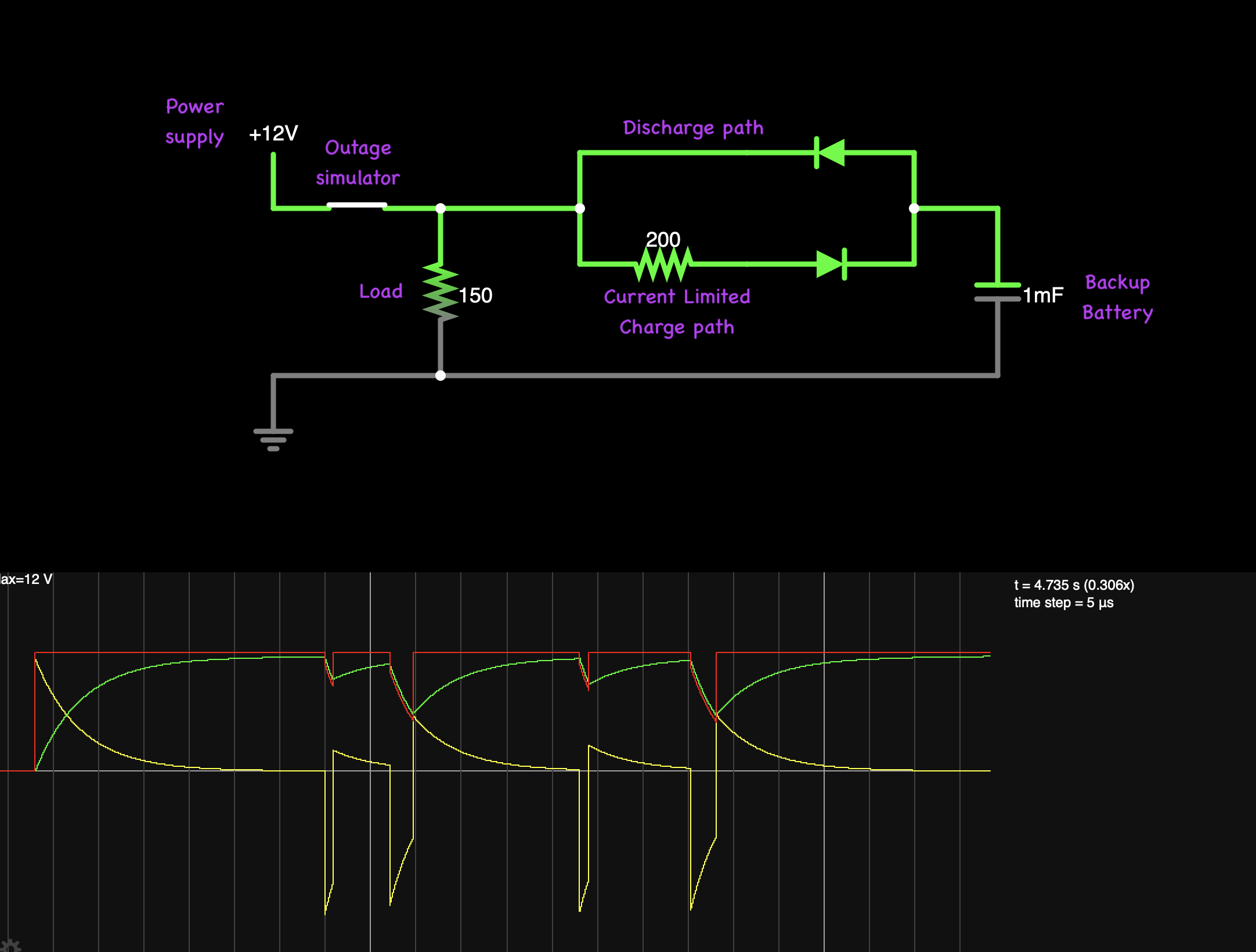
I have simulated opposing parallel diodes, where the charge direction has a resistor, and that seems to work the way I want. Maybe a regulator (lm317?) in “CC mode” would be even better. Either way, I’m concerned about diode forward voltage.

screenshot of prototype circuit design in simulator

In any case, I don’t really want to go to the trouble of designing and building a bespoke circuit if this wheel is already invented.

I have an electronic door lock that takes mains power, and steps it down to the 12V DC used for its lock mechanism and for signalling.

Because it’s “fail safe” (unlocks when power is removed), I would like to add a small backup battery to it.

I have checked that I can directly power it by providing the 12V power to the appropriate pins, with a 3S (“12.6V”) lithium ion battery. The mains power is not required for operation.

This would cover short outages, because the 12V supply will keep the battery charged, and the battery will discharge 12V while the power is out. A bit like a mega coupling capacitor.

However, if the battery discharges significantly during a longer outage, when power is restored, the lock’s supply will work very hard against the battery’s discharged state, possibly damaging or tripping the supply.

The battery will also charge too fast from its lowest state of charge. It has a BMS, but doesn’t provide a charging circuit, it’s only for safety (eg over current).

What I would like is a circuit that allows current to freely flow during discharge, but be current-limited (~100–500 mA) during charge. Is there an off the shelf “one way charging” module, or a simple circuit I can build?

I have simulated opposing parallel diodes, where the charge direction has a resistor, and that seems to work the way I want. Maybe a regulator (lm317?) in “CC mode” would be even better. Either way, I’m concerned about diode forward voltage.

In any case, I don’t really want to go to the trouble of designing and building a bespoke circuit if this wheel is already invented.

I have an electronic door lock that takes mains power, and steps it down to the 12V DC used for its lock mechanism and for signalling.

Because it’s “fail safe” (unlocks when power is removed), I would like to add a small backup battery to it.

I have checked that I can directly power it by providing the 12V power to the appropriate pins, with a 3S (“12.6V”) lithium ion battery. The mains power is not required for operation.

This would cover short outages, because the 12V supply will keep the battery charged, and the battery will discharge 12V while the power is out. A bit like a mega coupling capacitor.

However, if the battery discharges significantly during a longer outage, when power is restored, the lock’s supply will work very hard against the battery’s discharged state, possibly damaging or tripping the supply. Or at least causing enough voltage drop that could cause problems.

(I was worried that the battery may also charge too fast from its lowest state of charge, but I think it has a BMS, including a charge and balance circuit.)

What I would like is a circuit that allows current to freely flow during discharge, but be current-limited (~100–500 mA) during charge. Is there an off the shelf “one way charging” module, or a simple circuit I can build?

I have simulated opposing parallel diodes, where the charge direction has a resistor, and that seems to work the way I want. Maybe a regulator (lm317?) in “CC mode” would be even better. Either way, I’m concerned about diode forward voltage.

screenshot of prototype circuit design in simulator

In any case, I don’t really want to go to the trouble of designing and building a bespoke circuit if this wheel is already invented.

Source Link
aaaidan
  • 563
  • 1
  • 8
  • 17

One way charge circuit

I have an electronic door lock that takes mains power, and steps it down to the 12V DC used for its lock mechanism and for signalling.

Because it’s “fail safe” (unlocks when power is removed), I would like to add a small backup battery to it.

I have checked that I can directly power it by providing the 12V power to the appropriate pins, with a 3S (“12.6V”) lithium ion battery. The mains power is not required for operation.

This would cover short outages, because the 12V supply will keep the battery charged, and the battery will discharge 12V while the power is out. A bit like a mega coupling capacitor.

However, if the battery discharges significantly during a longer outage, when power is restored, the lock’s supply will work very hard against the battery’s discharged state, possibly damaging or tripping the supply.

The battery will also charge too fast from its lowest state of charge. It has a BMS, but doesn’t provide a charging circuit, it’s only for safety (eg over current).

What I would like is a circuit that allows current to freely flow during discharge, but be current-limited (~100–500 mA) during charge. Is there an off the shelf “one way charging” module, or a simple circuit I can build?

I have simulated opposing parallel diodes, where the charge direction has a resistor, and that seems to work the way I want. Maybe a regulator (lm317?) in “CC mode” would be even better. Either way, I’m concerned about diode forward voltage.

In any case, I don’t really want to go to the trouble of designing and building a bespoke circuit if this wheel is already invented.