0
\$\begingroup\$

I have an electronic door lock that takes mains power, and steps it down to the 12V DC used for its lock mechanism and for signalling.

Because it’s “fail safe” (unlocks when power is removed), I would like to add a small backup battery to it.

I have checked that I can directly power it by providing the 12V power to the appropriate pins, with a 3S (“12.6V”) lithium ion battery. The mains power is not required for operation.

This would cover short outages, because the 12V supply will keep the battery charged, and the battery will discharge 12V while the power is out. A bit like a mega coupling capacitor.

However, if the battery discharges significantly during a longer outage, when power is restored, the lock’s supply will work very hard against the battery’s discharged state, possibly damaging or tripping the supply. Or at least causing enough voltage drop that could cause problems.

(I was worried that the battery may also charge too fast from its lowest state of charge, but I think it has a BMS, including a charge and balance circuit.)

What I would like is a circuit that allows current to freely flow during discharge, but be current-limited (~100–500 mA) during charge. Is there an off the shelf “one way charging” module, or a simple circuit I can build?

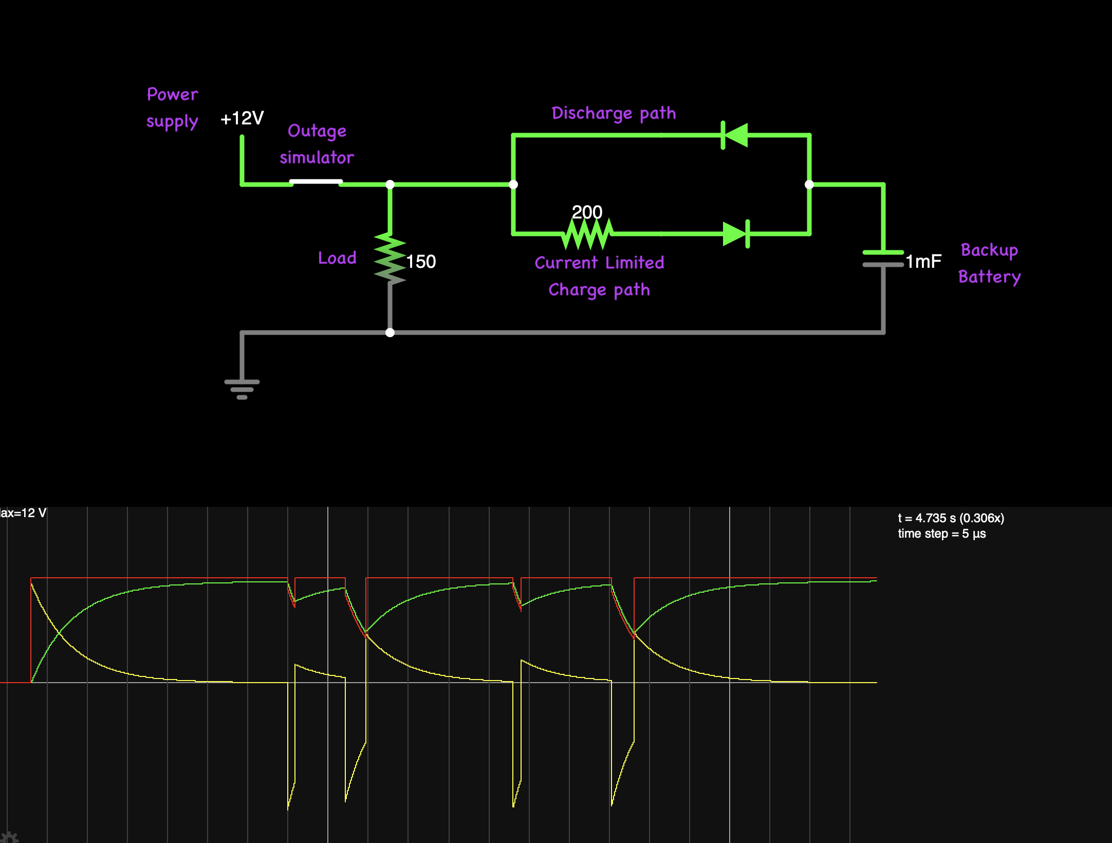
I have simulated opposing parallel diodes, where the charge direction has a resistor, and that seems to work the way I want. Maybe a regulator (lm317?) in “CC mode” would be even better. Either way, I’m concerned about diode forward voltage.

screenshot of prototype circuit design in simulator

In any case, I don’t really want to go to the trouble of designing and building a bespoke circuit if this wheel is already invented.

\$\endgroup\$
1
  • \$\begingroup\$ there's a whole bunch of DIY (and cheap turn-key modules) circuits for a "12V UPS". Even less-effort, a sub $20 solar charge controller fed solid DC instead of PV would work a treat with lifepo4 or SLA batteries. Most home-brew charging circuits are less than ideal for battery longevity, but does that matter to you? \$\endgroup\$
    – dandavis
    Commented Nov 15 at 21:06

1 Answer 1

0
\$\begingroup\$

Your problem isn't the diode drop. Your problem is you need a real battery charger. For you application, a small lead acid battery could float charge when idle and provide the current when needed. You simply place the battery in parallele with the lock and the 12V power supply. No charger necessary (think: same way tradition automobiles have been doing it for a hundred years). If you're concerned with charge current being to high, then your current-limiting charge resistor/anti-parallel diode is a good idea.

Lithium-Ion or pretty much any other battery chemistry is going to need a real charger. There's no diode resistor trick that would be acceptable.

\$\endgroup\$
4
  • \$\begingroup\$ Thanks, good insights. Thinking about it, I'm pretty sure the battery I'm using has a charger built in, because it's a 3S Lithium battery, but there is only a +/- barrel jack. This suggests there is internal balancing, which is typically only done with a dedicated charger. This also suggests there's probably a CC feature to prevent damage to the battery. I'm just more concerned about the power supply being drawn too much. \$\endgroup\$
    – aaaidan
    Commented Nov 15 at 20:10
  • \$\begingroup\$ You say "the anti-parallel diode is a good idea". Do you know of any product I could buy for this, or a precedent (like a circuit diagram)? \$\endgroup\$
    – aaaidan
    Commented Nov 15 at 20:12
  • \$\begingroup\$ @aaaidan If the battery has an internal charger, you simply can't starve the charger of current to simply reduce the peak current - the charger will malfunction. The peak current, or charging current, is inherent to the charger. So the internal charger would have to be adjusted/modified. I don't recommend doing that as these are typically "factory set" and you will need a great understanding of the internal charging circuitry to attempt such mods. Battery could explode if it's done wrong. \$\endgroup\$
    – MOSFET
    Commented Nov 15 at 20:21
  • \$\begingroup\$ The anti-paralle diode resistor was only relevant to the float-charge Lead acid battery idea. There are no parts that have the resistor and diode as one package - they are discrete components. The arrangement is the same as in the circuit you added, however, you can reduce it down to just one resistor and one diode. \$\endgroup\$
    – MOSFET
    Commented Nov 15 at 20:24

Your Answer

By clicking “Post Your Answer”, you agree to our terms of service and acknowledge you have read our privacy policy.

Not the answer you're looking for? Browse other questions tagged or ask your own question.