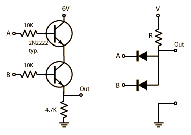
I drew an AND gate as follows which mimics this diagram.this diagram:
   --- +6V (A)
    |
i1-<
    |
i2-<
    |- out
    v
    ground (B)

(source)
I understand how current flows between A and B(when both inputs are logical 1) because there is difference of voltage, maybe 6V, and AFAIK A and B are possibly connected making a circular circuit(at least via earth).
But I don't understand how current can flow from some signal sources to two transistors to manipulate transistors. There seems no difference of voltage regarding i1 and i2. I want to know the entire circuit diagram including the signal sources.
PS. Are there 3 separate circuits containing i1, i2, A-B, respectively?
