added 141 characters in body
Source Link

I've got a sensor that outputs a .7Vpp square wave at 36kHz-60kHz. I need to take that square wave and amplify it to 5Vpp, as close to 0V to 5V rails as possible. Then I need to send that signal over a long cable, 6-50 feet depending on where I'm using the sensor and have that square wave still be nice and square when it reaches the other end.

I have a single +5VDC supply to work with.

Currently I can get a good square wave by using an LM311P comparator, but when I try to drive it over a long cable I end up with a wave that looks like a shark fin.

Should I be taking a different approach all together instead of the comparator, or is there something I can put between the comparator and the long cable to help the signal?

This is a little bit of a simplification of what I'm doing, but it's basically what I'm doing now. NOTE: the BJT shown is actually part of the LM311P comparator. Also, the 1V source is actually 5V.
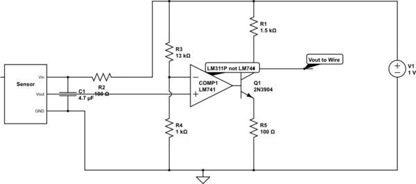
schematic

simulate this circuit – Schematic created using CircuitLab

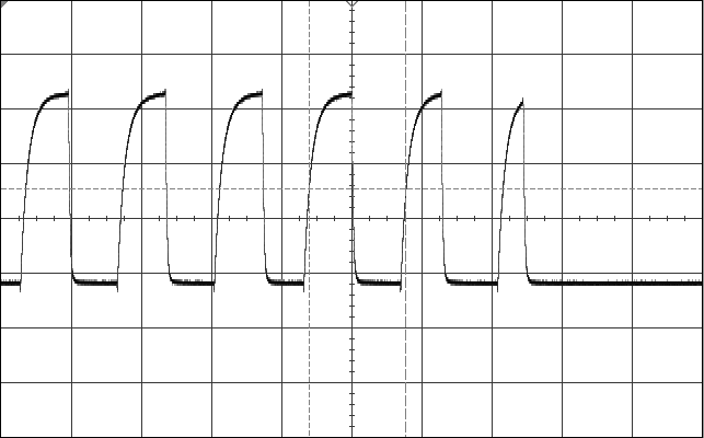
Here's the shark fin output at 36kHz, about 5Vpp, that I was describing: Shark Fin Wave
I've got a sensor that outputs a .7Vpp square wave at 36kHz-60kHz. I need to take that square wave and amplify it to 5Vpp, as close to 0V to 5V rails as possible. Then I need to send that signal over a long cable, 6-50 feet depending on where I'm using the sensor and have that square wave still be nice and square when it reaches the other end.

I have a single +5VDC supply to work with.

Currently I can get a good square wave by using an LM311P comparator, but when I try to drive it over a long cable I end up with a wave that looks like a shark fin.

Should I be taking a different approach all together instead of the comparator, or is there something I can put between the comparator and the long cable to help the signal?

This is a little bit of a simplification of what I'm doing, but it's basically what I'm doing now. NOTE: the BJT shown is actually part of the LM311P comparator. Also, the 1V source is actually 5V.

schematic

simulate this circuit – Schematic created using CircuitLab

Here's the shark fin output at 36kHz, about 5Vpp, that I was describing: Shark Fin Wave

Source Link

Amplify .7Vpp square wave to 5Vpp square wave buffered to go over a 15-50 foot cable

I've got a sensor that outputs a .7Vpp square wave at 36kHz-60kHz. I need to take that square wave and amplify it to 5Vpp, as close to 0V to 5V rails as possible. Then I need to send that signal over a long cable, 6-50 feet depending on where I'm using the sensor and have that square wave still be nice and square when it reaches the other end.

I have a single +5VDC supply to work with.

Currently I can get a good square wave by using an LM311P comparator, but when I try to drive it over a long cable I end up with a wave that looks like a shark fin.

Should I be taking a different approach all together instead of the comparator, or is there something I can put between the comparator and the long cable to help the signal?

This is a little bit of a simplification of what I'm doing, but it's basically what I'm doing now. NOTE: the BJT shown is actually part of the LM311P comparator. Also, the 1V source is actually 5V.

schematic

simulate this circuit – Schematic created using CircuitLab