0
\$\begingroup\$

Continuing my learning expedition, I've decided to use the LM3S5R36-IQR80-C3 ARM Cortex-M3 MPU, to try and learn to build my own little experiment PCB, almost like the Teensy 3.0. The idea is to learn the entire process of designing the PCB from scratch.

I've come up with the following circuit so far, working on ESD protection for the USB port, as well as the 3.3V supply for the Vdd pins on the ARM chip.

I'm a hobbyist, so I have no electronics degree or background, so I'm using the datasheets for the ESD array I selected, as well as the voltage regulator, to hopefully get a steady 3.3V voltage supply from the 5V USB Vbus.

Here's my circuit so far (if it's broken, it's coz I had no help, except Google) :
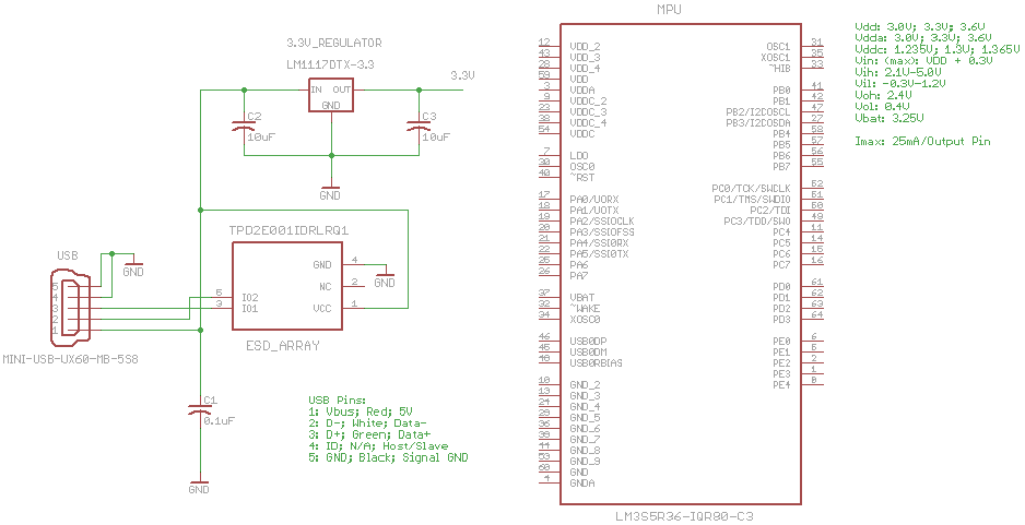
My ARM circuit board

I'm not sure if I can ask here whether the circuit looks right or not, I am looking for some constructive criticism, however. So feel free to comment, or refer me to a site where I can have my circuit scrutinized by the community.

More, importantly, let me state my actual question...

My next step is to start connecting the 3.3V supply from the regulator, to the ARM chip's Vdd and Vddc pins to the 3.3V supply. The thing I want to know is, how I can be sure I am not pulling too much current through the regulator or the USB 5V Vbus. The last thing I want is to sit with a bunch of scorched spares and a broken USB port on my Mac.

There are 4 Vdd and 4Vddc pins, so I understand I can get the 3.3V to each pin, by simply connecting them to the supply in parallel. This however, depending on the resistance the chip causes between the 3.3V and GND, makes it tricky, and I'm not sure how to go about making sure I don't draw too much current.

I guess it comes down to how much current the ARM chip sinks, but I'm not sure how to effectively work this out.

I hope my question makes, sense, feel free to edit to clarify it.

\$\endgroup\$

3 Answers 3

1
\$\begingroup\$

Technically For USB, you should typically draw no more than 100mA, unless you're enumerating the device and specifically asking to draw higher current. According to the spec, you can enumerate yourself and request up to 500mA in USB 2.0 spec. However, these limitations are rarely enforced physically, meaning that usually you will be able to draw until some circuitry in the PC limits you. So, in general, less than 500mA is safe.

The voltage regulator you chose is an older regulator that has very little short circuit protection, reverse voltage protection, overheating protection, etc. I suggest you select a more modern part that can do what you need and includes all of these things. Note that the microcontroller will likely need direct connection to the USB VCC. Selecting the 3.3V regulator, you need to take into account primarily output current and dissipation (Aside from the obvious fixed voltage output and a Vin that includes 5V), although for 500mA it's not that big of a concern.

Your circuit needs a fuse as well. Select a fast acting fuse. Also, I didn't see the typical ferrite bead and decoupling capacitors that are usually added. Your microcontroller likely needs direct connection to 5V bus to be able to operate with USB, so check the reference circuit for the part you're using.

Finally, if you're that worried about your Mac at first, power the board using some AC to 5V converter like the ones used for charging phones. Measure the current and make sure that the it's ok. Also, always measure whether there's a short circuit between the USB Bus VCC and GND before connecting it to anything.

The ARM processor you're using will be much less than the limit. Look at its datasheet on page 1013, it tells you that at 80MHz fully running it is 90mA. Add the extra stuff and GPIOs to it and USB is plenty.

\$\endgroup\$
2
  • \$\begingroup\$ Looking at RS Electronics' website, I'm not sure which voltage regulator to pick, there are 1000's of options!!! \$\endgroup\$ Commented Jan 11, 2013 at 21:31
  • \$\begingroup\$ @josef.van.niekerk Wouldthere be an issue for you to order some samples from TI? Also, do you have a limitation for packages? Otherwise, I could recommend many. For example, TPS79530 from TI. RS Electronics seems very limited in their selection. \$\endgroup\$ Commented Jan 11, 2013 at 22:58
3
\$\begingroup\$

The largest value I can find in the datasheet for the ARM is 126ma when running flat out and peripherals on. This is unlikely to cause problems. If you're very worried you can buy desktop power supplies with current limiters. At the very least, when powering it up for the first time use a phone charger not a computer and have a suitably-ranged current meter in the positive line.

Are you intending to connect the ARM to the USB? There will be a reference circuit for that - use it. That bit also requires careful PCB design.

I would start with a reference design for the Stellaris - there's a cheap dev board available for it - and work through understanding why everything is there. If you decide you don't need it, remove it.

(These parts aren't as forgiving and easy to use as PICs / AVRs, and therefore less likely to produce a working circuit)

\$\endgroup\$
1
  • \$\begingroup\$ I agree on the forgiving part, it's definitely harder to do ARM stuff, but the rewards are so big! \$\endgroup\$ Commented Jan 11, 2013 at 20:44
2
\$\begingroup\$

If the USB port follows the USB standard, it is current limited. There is a default minimum current limit, and USB device need to negotiate for more as part of the enumeration process. Even with the extra current negotiation, there is a reasonable maximum. The USB port should be unable to output more current than that. My windows OS warns me when something is trying for extra, but I'm not sure if you'll see the message on a mac.

\$\endgroup\$
1
  • 1
    \$\begingroup\$ Look at my post. Most PCs don't physically limit USB current until it is very much near the limit, much higher than 500mA usually. Which is why USB fans and other gadgets work without enumerating. \$\endgroup\$ Commented Jan 11, 2013 at 16:25

Your Answer

By clicking “Post Your Answer”, you agree to our terms of service and acknowledge you have read our privacy policy.

Not the answer you're looking for? Browse other questions tagged or ask your own question.