5
\$\begingroup\$

I need to interface an LDR with a microcontroller.

While searching for some circuit ideas on the internet, I came across two different ideas:

  • One was using a voltage divider circuit with another resistor and input that into the ADC port of a microcontroller.

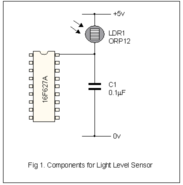
  • Another was to couple the LDR to ground via small capacitor and connect the other end directly to a microcontroller. (I am not sure how this works?)

    For example:

    schematic for measuring light using LDR without an ADC

    Image source: Measuring Light on a PIC 16F62x from Robot Builder

    The PIC 16F62X series is a pin-compatible upgrade to the old F84 offering lots of extra internal goodies such as timers, a USART and a couple of comparators. There are no analogue to digital converters (ADC) as such but it is a simple job to use a comparator, a timer and a few lines of software to make one.

Which one is more accurate?

\$\endgroup\$
6
  • 3
    \$\begingroup\$ Can you provide resource (scheme) for the second circuit. \$\endgroup\$
    – aiao
    Commented Feb 13, 2013 at 12:46
  • 1
    \$\begingroup\$ accurate in what sense? what are you trying to accomplish? \$\endgroup\$
    – miceuz
    Commented Feb 13, 2013 at 12:52
  • 1
    \$\begingroup\$ +1 on both above, but go option 1 if you have an ADC available. Very likely more accurate and much easier to understand / program. \$\endgroup\$
    – PeterJ
    Commented Feb 13, 2013 at 12:56
  • \$\begingroup\$ @miceuz accurate for sun angle measurement. \$\endgroup\$
    – iamgopal
    Commented Feb 14, 2013 at 2:41
  • \$\begingroup\$ robotbuilder.co.uk/Resources/Articles/149.aspx @aiao \$\endgroup\$
    – iamgopal
    Commented Feb 14, 2013 at 2:44

1 Answer 1

5
\$\begingroup\$

This is very simple:

Since both the voltage into the A/D input and the A/D's measuring range is relative to the PWR voltage, the PWR voltage cancels out. The A/D pin voltage will be non-linear with light intensity. Make R2 the value R1 has in the center of its range or where you want the most resolution.

\$\endgroup\$
1
  • 3
    \$\begingroup\$ @gopal - Just to add a little something: when I'm using a high-ish impedance sensor like this, I like to add a little capacitor (10nF - 100nF) between the A/D input and GND. This helps to charge the ADC's sample and hold capacitor more reliably, and also acts as a simple low pass filter. You'll get a better signal/noise ratio this way. \$\endgroup\$ Commented Feb 13, 2013 at 17:15

Your Answer

By clicking “Post Your Answer”, you agree to our terms of service and acknowledge you have read our privacy policy.

Not the answer you're looking for? Browse other questions tagged or ask your own question.