9
\$\begingroup\$

I have a fuel sender in my kit car that goes from 20R to earth (full) to 200R (empty). Unfortunately the gauge (constant current source, measuring resistance to earth?) expects empty to be 240 ohms, so displays '1/4 full' when empty. What is the simplest analogue way to make 20-200R look like 20-240R?

(40R in series gives a full tank showing '3/4 full' on the dial: Still not ideal!).


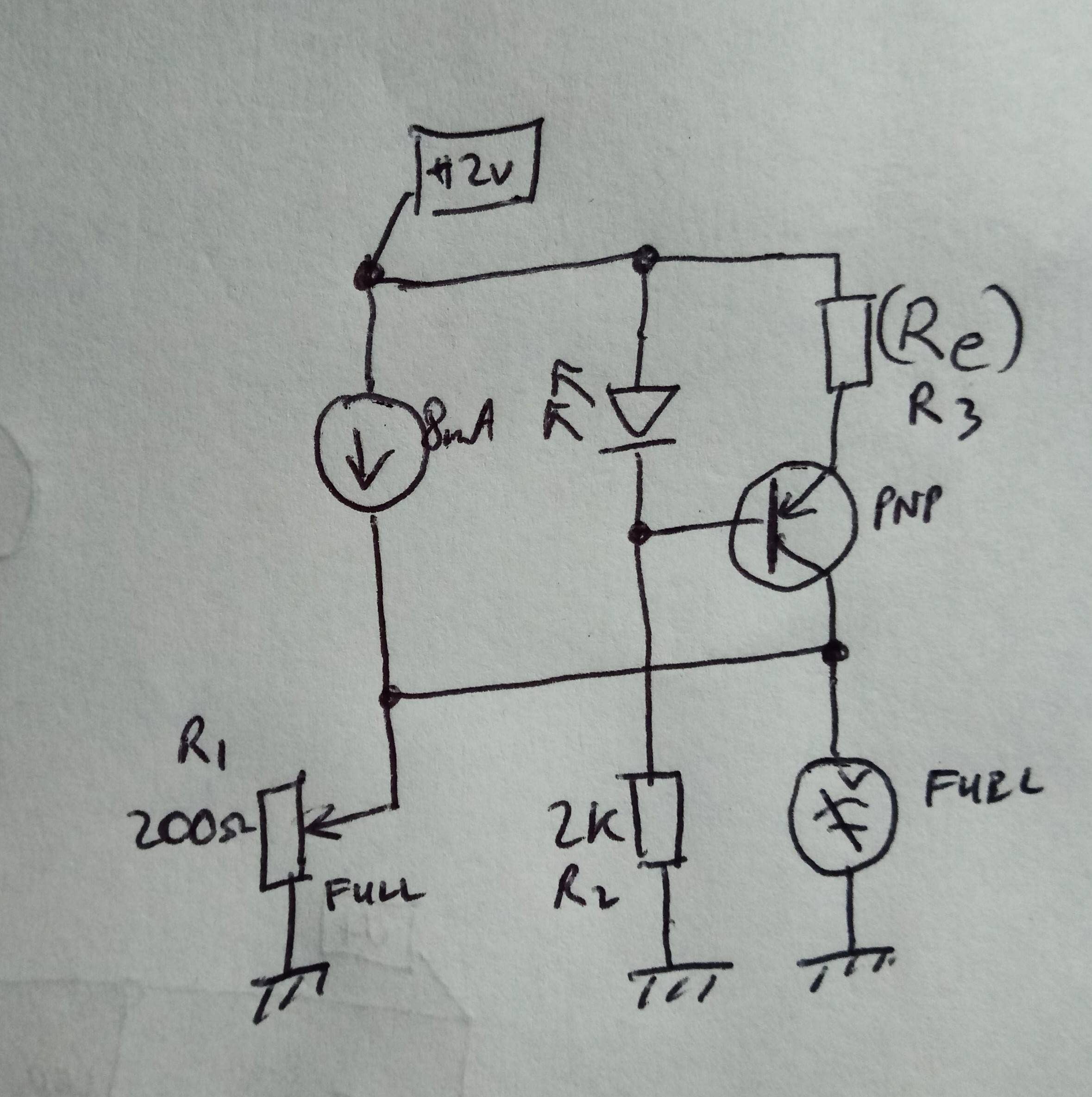
So, a great suggestion from Transistor (below). I think I'll change R4 in his/her Figure 1 to a constant current source since car volts can vary quite a lot!

enter image description here

I believe the value for R3 (above) will be fairly independent of the transistor specs?

Update: Yes, this works nicely, gauge now goes from full to zero. I put R3 on a little trimmer - 720R for 1.6mA. Many thanks transistor!

\$\endgroup\$
9
  • \$\begingroup\$ If you want to modify what you have, you need to know the full details on the gauge. \$\endgroup\$
    – user80875
    Commented May 30, 2019 at 14:47
  • \$\begingroup\$ Find a different gauge or a different sensor. Are they aftermarket units? Can they be reworked? \$\endgroup\$
    – TimWescott
    Commented May 30, 2019 at 14:48
  • 7
    \$\begingroup\$ It may be the best you can do easily without changing the gauge. Empty is the important point on the dial anyway. \$\endgroup\$ Commented May 30, 2019 at 14:52
  • 1
    \$\begingroup\$ Measurements show it to be a linear pot, 20ohms at one end, 200 at the other (110 in the middle). It's a digital gauge that runs about 8mA into the resistor in all positions. \$\endgroup\$ Commented May 30, 2019 at 15:25
  • 2
    \$\begingroup\$ A digital gauge without adjustable settings for empty and full sounds like a underwhelming digital gauge. \$\endgroup\$ Commented May 31, 2019 at 0:11

5 Answers 5

14
\$\begingroup\$

I have a fuel sender in my kit car that goes from 20R to earth (full) to 200R (empty). Unfortunately the gauge (constant current source, measuring resistance to earth?) expects empty to be 240 ohms, so displays '1/4 full' when empty.

Status   Spec.   Actual   Reading  Voltage
------------------------------------------
Full       20 Ω    20 Ω   100%      160 mV
Empty     240 Ω   200 Ω    25%     1600 mV
                  Required voltage 1920 mV

schematic

simulate this circuit – Schematic created using CircuitLab

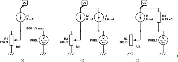
Figure 1. (a) What you've got. (b) The voltage reading can be boosted to the correct level by feeding an extra 1.6 mA through the sensor. (c) A simple current source based on 12 V supply and 1920 mV for empty.

What is the simplest analogue way to make 20-200R look like 20-240R?

R4 looks simple to me.

I suspect that the 8 mA source is constant current so that the gauge doesn't fluctuate with revving of the engine (other than that gradual downward trend as you burn up the earth's carbon fuel reserves). To avoid R4 introducing variation you might want to feed it from a stable voltage source - as high as you reasonably can - and recalculate for your new voltage.

At full the extra 1.6 mA will increase the voltage through the 20 Ω by 32 mV. On a span of (1920 - 160 =) 1760 mV this represents an error of 36 / 1760 = 2% so with a full tank it will read about 98%. This should be acceptable.

\$\endgroup\$
4
  • \$\begingroup\$ That looks just the ticket! I'll give it a whirl, thanks. \$\endgroup\$ Commented May 30, 2019 at 20:14
  • \$\begingroup\$ Rather than regulating the voltage for R4, I can just add a transistor to make a constant-current source, I think? \$\endgroup\$ Commented May 31, 2019 at 7:11
  • \$\begingroup\$ Sure. Post a schematic as an update to your question (referencing my answer) and we'll review it. I've updated the answer with an error calculation. \$\endgroup\$
    – Transistor
    Commented May 31, 2019 at 7:15
  • \$\begingroup\$ So, a great suggestion from Transistor (above). If I change R4 to a constant current source: Transistor's suggestion, with a constant current source since car Volts can vary quite a lot! I believe the value for R3 will be fairly independent of the transistor specs? \$\endgroup\$ Commented May 31, 2019 at 8:55
6
\$\begingroup\$

I think the easiest way would be just getting a new variable resistor. You could use a transistor to switch in an extra resistance but potentiometers are pretty cheap, so swapping out would be the easiest option.

\$\endgroup\$
4
  • \$\begingroup\$ indeed. its a gas gauge so you want some semblance of linearity and simple solutions will not provide that. that would require transistors to amplify and offset a voltage tuned by the pot and then used to drive a voltage controlled resistor. \$\endgroup\$
    – DKNguyen
    Commented May 30, 2019 at 14:45
  • 1
    \$\begingroup\$ Since the potentiometer is an integral part of a fuel level sensor, it may not be practical either to find a suitable replacement or to get access to replace it. \$\endgroup\$ Commented May 30, 2019 at 16:37
  • \$\begingroup\$ @pericynthion However, the entire fuel level sensor may be a replaceable item. \$\endgroup\$
    – TimWescott
    Commented May 30, 2019 at 16:38
  • 1
    \$\begingroup\$ That's where this started - the original ran from 70-140 ohms, so I replaced with an unused item, that still is clearly some way off spec! \$\endgroup\$ Commented May 30, 2019 at 17:31
4
\$\begingroup\$

Per your comment "It's a digital gauge that runs about 8mA into the resistor in all positions", you don't actually need to make it "look like a resistor" from the gauge's point of view - you can just provide the gauge with a low-impedance voltage source, where that voltage is a linear function of the sensor resistance. A fairly straightforward op amp circuit should do the trick. You'll want to output a voltage that's 20*.008=0.16 V at one end of the scale and 240*.008=1.920 V at the other end of the scale.

\$\endgroup\$
1
  • \$\begingroup\$ Thanks - I was thinking of something around an op-amp, just wondered if there was something more elegant (related to a current mirror?) that anyone one of. \$\endgroup\$ Commented May 30, 2019 at 16:40
2
\$\begingroup\$

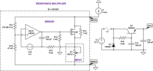
Here's a resistance multiplier with a 240/200 ratio. No need for reference voltages, the ratio is set with two resistors. The negative resistor end can float up to several volts above ground. The multiplier works across a wide range of currents, from a fraction of mA - where it gets quite slow - to about as much as M1 and R1 can dissipate.

schematic

simulate this circuit – Schematic created using CircuitLab

The parts can be jellybean: LM324, 1N4148, BSS138. 2N7000 might work too. C10 can be potentially increased for better stability.

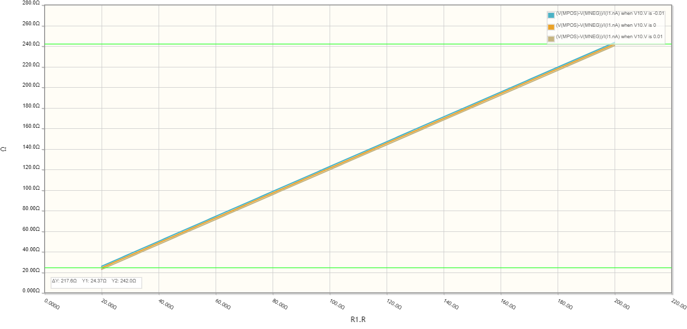
The circuit is fairly accurate. Accuracy is mainly determined by resister tolerances. Op-amp's input offset adds a +/-3 ohm resistance offset worst case.

The transfer curve, from R1's resistance to the resistance seen at the output, is as shown below, for -10mV, 0, and +10mV op amp offset (worst case limits).

The transfer curve with limits due to op-amp offset

\$\endgroup\$
1
\$\begingroup\$

There's no easy way to do it, anyway. You could add a 20ohm fixed in series with a 20-220 ohm sensor, to give 40-240. Not quite full, but empty would be empty.

If the sender truly is 20-200, something is wrong for the gauge to expect 240. Bend the float arm up?

Are you sure true fuel "empty" is the full travel of the sensor? The simple solution is to add fixed resistance to achieve true empty, and just recognize that 90% represents full.

It's doubtful the gauge will respond in a perfectly linear fashion anyway, unless your gas tank is a perfect square or vertical cylinder.

\$\endgroup\$

Your Answer

By clicking “Post Your Answer”, you agree to our terms of service and acknowledge you have read our privacy policy.

Not the answer you're looking for? Browse other questions tagged or ask your own question.