0
\$\begingroup\$

schematic

simulate this circuit – Schematic created using CircuitLab

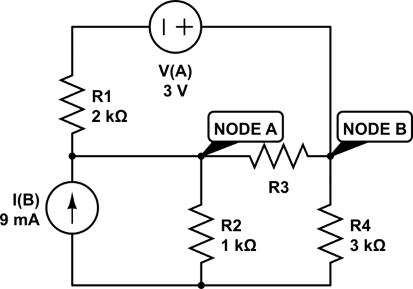
I have gotten really stuck on this question. The question is:

  1. Determine R3 so that maximum power is consumed in R3.
  2. What is that maximum power? Answer in microwatts.

I am not sure where to begin. I have begun my naming the R3 as R(Load) and calculating I(Short) from Node A to Node B by just putting a wire there instead of R3, but I am not able to get the voltages in the nodes. I am really confused and hoping for some guidance.

\$\endgroup\$
4
  • \$\begingroup\$ (My first thought: \$R_{source} = R_{load}\$.) \$\endgroup\$
    – greybeard
    Commented Aug 5, 2023 at 13:59
  • \$\begingroup\$ What do you mean by R(Source)? What is R(Source)? \$\endgroup\$ Commented Aug 5, 2023 at 14:01
  • \$\begingroup\$ Take finding \$R_{source}\$ as the exercise. \$\endgroup\$
    – greybeard
    Commented Aug 5, 2023 at 14:02
  • \$\begingroup\$ Sorry, what does source resistance mean? \$\endgroup\$ Commented Aug 5, 2023 at 14:04

3 Answers 3

1
\$\begingroup\$

This is a standard network reduction task: note that you get maximum power delivery to a component by matching the internal resistance of a voltage/current source feeding it.

So you go about reforming the network. Replace I(B) paralleled with R2 with a 9V voltage source in series with R2, then add R4 into it. Essentially, you now have two voltage sources connected in parallel to R3, one with an internal resistance of 4kohm, one with 2kohm, making for a total of 1.33kohm, so that is what R3 needs to be in order to maximize power output into it.

It's left as an exercise to the reader to calculate the actual amount of power, but you have to be aware that the current source and the voltage source have opposing polarity, so the resulting voltage/power will not be all that impressive (at least it isn't zero in which case the value of R3 would be actually irrelevant).

\$\endgroup\$
5
  • \$\begingroup\$ Thanks! How did you calculate 1.33 kohm? What formula did you use? \$\endgroup\$ Commented Aug 5, 2023 at 14:14
  • \$\begingroup\$ Paralleling 2kohm and 4kohm is absolutely basic. I happened to add 1/2 and 1/4 with a result of 3/4 which you then invert again. It's also possible as (2·4)/(2+4). Calculating the total resistance of paralleled resistors is basic enough that you should be able to do it in your sleep if you frequently need to rearrange circuit networks. \$\endgroup\$
    – user107063
    Commented Aug 5, 2023 at 14:21
  • \$\begingroup\$ Yes, I understand the formula now. I have seen it before. What made you calculate them in parallel? Why is that relevant to Source resistance? Thank you so much! \$\endgroup\$ Commented Aug 5, 2023 at 14:24
  • \$\begingroup\$ Like what did you do with R3, did you just ignore it? \$\endgroup\$ Commented Aug 5, 2023 at 14:25
  • \$\begingroup\$ R3 is your consumer. You can replace a non-singular network of voltage and current sources and resistors with a single voltage source and a series resistor or equivalently with a single current source and a parallel resistor. View everything but R3 as a voltage source with internal resistance. When paralleling two different voltage sources, the joint internal resistance is the parallel of the individual internal resistances, with the equivalent voltage of the unloaded circuit. Essentially for calculating the internal resistance, you can replace all voltage sources with short circuits. \$\endgroup\$
    – user107063
    Commented Aug 5, 2023 at 14:30
1
\$\begingroup\$

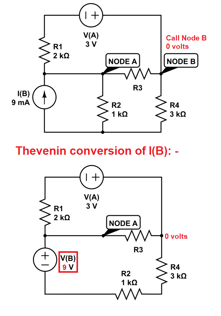
It's always a bit messy trying to work with both current and voltage sources so convert I(B) and R2 to an equivalent voltage source V(B) and redraw: -

enter image description here

Then join R2 and R4 together to make 4 kΩ and place on the other limb of V(B).

Now you have two voltage sources commoned to 0 volts and each has a series single resistor. From here you can go several ways but pretty much all ways include source transformation (that's what I did with I(B) making it V(B) btw.

Is this enough of a hint to figure out the rest yourself? Do you understand what the R3 resistance needs to be to get maximum power transfer?

\$\endgroup\$
5
  • \$\begingroup\$ Hi! Thank you so much for your response! I understand the conversion of the circuit, what I don't understand is the R(Load). Should Calculate I(Short circuit) and then V(A)-V(B)? Becuase my results from that don't add up... \$\endgroup\$ Commented Aug 5, 2023 at 14:13
  • \$\begingroup\$ No, you don't do that, you should consider combining the two voltage sources, R1, R2 and R4 into one voltage source and one resistor. \$\endgroup\$
    – Andy aka
    Commented Aug 5, 2023 at 15:02
  • \$\begingroup\$ @Andyaka If you like conversions, you can first convert both voltage sources into current sources, add their currents and inverse resistances to get a single current source, then (optionally) convert that back into a single voltage source for the final flourish. \$\endgroup\$
    – user107063
    Commented Aug 5, 2023 at 20:22
  • \$\begingroup\$ That's easy to say after the event of course. But, by simple examination of my altered circuit, the value for R3 is plainly obvious. Can you see that @user107063 \$\endgroup\$
    – Andy aka
    Commented Aug 5, 2023 at 20:56
  • \$\begingroup\$ @Andyaka Sure, see my own answer. But that does not yet give you the wattage, and the flip-flopping conversions are one way to combine the two voltage sources into one. \$\endgroup\$
    – user107063
    Commented Aug 5, 2023 at 21:37
-1
\$\begingroup\$

First, I will present a method that uses Mathematica to solve this problem.

Well, we are trying to analyze the following circuit:
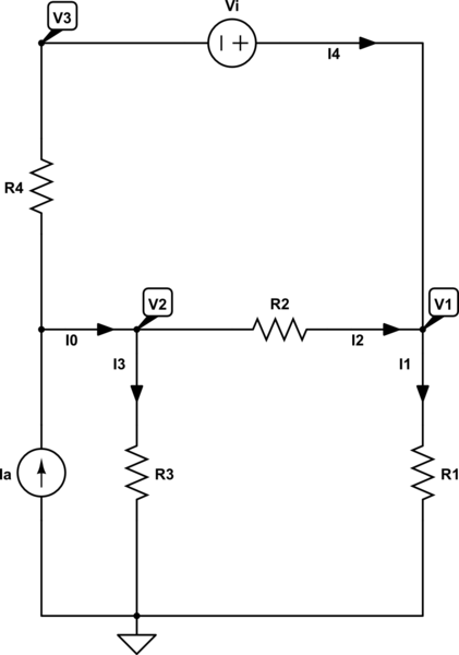
schematic

simulate this circuit – Schematic created using CircuitLab

When we use and apply KCL, we can write the following set of equations:

$$\begin{cases} \begin{alignat*}{1} \text{I}_\text{a}&=\text{I}_0+\text{I}_4\\ \\ \text{I}_0&=\text{I}_2+\text{I}_3\\ \\ \text{I}_1&=\text{I}_2+\text{I}_4\\ \\ \text{I}_\text{a}&=\text{I}_1+\text{I}_3 \end{alignat*} \end{cases}\tag1$$

When we use and apply Ohm's law, we can write the following set of equations:

$$\begin{cases} \begin{alignat*}{1} \text{I}_1&=\frac{\displaystyle\text{V}_1-0}{\displaystyle\text{R}_1}\\ \\ \text{I}_2&=\frac{\displaystyle\text{V}_2-\text{V}_1}{\displaystyle\text{R}_2}\\ \\ \text{I}_3&=\frac{\displaystyle\text{V}_2-0}{\displaystyle\text{R}_3}\\ \\ \text{I}_4&=\frac{\displaystyle\text{V}_2-\text{V}_3}{\displaystyle\text{R}_4} \end{alignat*} \end{cases}\tag2$$

We also know that \$\displaystyle\text{V}_1-\text{V}_3=\text{V}_\text{i}\$.

Now, we can solve for \$\displaystyle\text{V}_2-\text{V}_1\$:

$$\text{V}_2-\text{V}_1=\frac{\displaystyle\text{R}_2\left(\text{I}_\text{a}\text{R}_3\text{R}_4-\text{V}_\text{i}\left(\text{R}_1+\text{R}_3\right)\right)}{\displaystyle\text{R}_2\left(\text{R}_1+\text{R}_3\right)+\text{R}_4\left(\text{R}_1+\text{R}_2+\text{R}_3\right)}\tag3$$

Where I used the following Mathematica code to find \$(3)\$:

In[1]:=Clear["Global`*"];
solution = 
  FullSimplify[
   Solve[{Ia == I0 + I4, I0 == I2 + I3, I1 == I2 + I4, Ia == I1 + I3, 
     I1 == (V1 - 0)/R1, I2 == (V2 - V1)/R2, I3 == (V2 - 0)/R3, 
     I4 == (V2 - V3)/R4, V1 - V3 == Vi}, {I0, I1, I2, I3, I4, V1, V2, 
     V3}]];
FullSimplify[(V2 /. solution[[1]]) - (V1 /. solution[[1]])]

Out[1]=(Ia R2 R3 R4 - R2 (R1 + R3) Vi)/(R2 (R1 + R3) + (R1 + R2 + R3) R4)

So, the power in the resistor \$\text{R}_2\$ is given by:

$$\text{P}_{\text{R}_2}=\frac{\displaystyle\left(\text{V}_2-\text{V}_1\right)^2}{\displaystyle\text{R}_2}=\text{R}_2\left(\frac{\displaystyle\text{I}_\text{a}\text{R}_3\text{R}_4-\text{V}_\text{i}\left(\text{R}_1+\text{R}_3\right)}{\displaystyle\text{R}_2\left(\text{R}_1+\text{R}_3\right)+\text{R}_4\left(\text{R}_1+\text{R}_2+\text{R}_3\right)}\right)^2\tag4$$

In order to find the maximum, we can use:

$$\frac{\displaystyle\partial\text{P}_{\text{R}_2}}{\displaystyle\partial\text{R}_2}=0\space\Longleftrightarrow\space\text{R}_2=\frac{\displaystyle\text{R}_4\left(\text{R}_1+\text{R}_3\right)}{\displaystyle\text{R}_1+\text{R}_3+\text{R}_4}\tag5$$

Where I used the following Mathematica code to find \$(5)\$:

In[2]:=FullSimplify[
 Solve[{D[(
     R2 (Ia R3 R4 - (R1 + R3) Vi)^2)/(R2 (R1 + R3) + (R1 + R2 + 
          R3) R4)^2, R2] == 0}, R2]]

Out[2]={{R2 -> ((R1 + R3) R4)/(R1 + R3 + R4)}}

Using your values, we get:

$$\text{R}_2=\frac{\displaystyle2000\left(3000+1000\right)}{\displaystyle3000+1000+2000}=\frac{\displaystyle4000}{\displaystyle3}\approx1333.33\space\Omega\tag6$$

And the power is:

$$\text{P}_{\text{R}_2}=\frac{\displaystyle3}{\displaystyle16000}\approx0.0001875\space\text{W}\tag7$$
\$\endgroup\$
3
  • \$\begingroup\$ Why did you redraw the circuit and place the resistors in other places. R3 is what is asked not R2. Thanks a lot! \$\endgroup\$ Commented Aug 5, 2023 at 14:44
  • \$\begingroup\$ @DiodeLight97 well, I did just place the resistors as the simulator named them. The technique does not change when renaming the resistors. And your R3 is my R2. So study my answer before commenting please. Besides that, be happy that I took the time to answer it. You're welcome. \$\endgroup\$ Commented Aug 5, 2023 at 16:20
  • \$\begingroup\$ Can the one who downvoted, explain it. Good for my answers in the future. Thanks a lot. \$\endgroup\$ Commented Aug 5, 2023 at 22:31

Your Answer

By clicking “Post Your Answer”, you agree to our terms of service and acknowledge you have read our privacy policy.

Not the answer you're looking for? Browse other questions tagged or ask your own question.