0
\$\begingroup\$

I am currently designing a circuit, where output is switched on and off as obstacle passes IR (Infrared) beam, produced by IR LED and received by IR sensor (IR photo-transistor). The problem is that IR sensor is greatly affected by light from surrounding sources, like celling lamp. IR sensor's output is compared with comparator and if IR sensor is greatly illuminated by white light, comparator switches on the output as if IR LED would illuminate on sensor's surface.
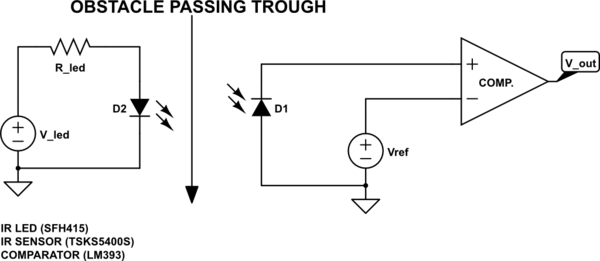
schematic

simulate this circuit – Schematic created using CircuitLab

Is it normal for IR sensor to react to visible light the same way it reacts to IR radiation?

This is kind of a problem since sensor of this circuit is constantly exposed to visible light and sometimes as an obstacle passes the IR beam, comparator just won't switch off the output because there is too much radiation from visible light.

Is there any other way to detect obstacle as it passes and breaks the IR beam of radiation without receiving part (sensor at input of comparator) being influenced by surroundings light sources, which produce visible light?

Both IR LED as sensor and IR sensor (photo-transistor) react the same way as they are being illuminated by visible light. I still don't get it why IR sensor detects visible light as it should only detect IR radiation, I think.

Would replacing IR LED and IR sensor with UV LED and UV sensor solve my issue?

\$\endgroup\$
10
  • \$\begingroup\$ You bothered drawing a schematic, so why wouldn't you giving us the part numbers? \$\endgroup\$
    – DKNguyen
    Commented Jul 3, 2019 at 21:35
  • \$\begingroup\$ UV won't help you. UV devices are very expensive and one of the reason is that UV is absorbed by almost everything that is cheap (plastic, glasses). \$\endgroup\$
    – DKNguyen
    Commented Jul 3, 2019 at 22:03
  • \$\begingroup\$ research TV remote controlls \$\endgroup\$
    – jsotola
    Commented Jul 4, 2019 at 0:20
  • \$\begingroup\$ @DKNguyen Just did. In response to your other comment, check SFH415. It consists of black colored plastic, which is most probably IR filter. Currently I am using it as emitter and receiver (sensor connected to comparator). With that filter, it acts the same way as TSKS5400S; generates voltage up to 1V if greatly illuminated with light bulb. So, I guess that filter doesn't help much. Any other ideas? \$\endgroup\$
    – lucenzo97
    Commented Jul 4, 2019 at 15:46
  • 1
    \$\begingroup\$ @Keno It is useful for both the phototransistor AND the LED to have a field of view only as wide as is necessary. It sees less of what you don't want to see and sees more of what you do want to see. It increases the signal-to-noise ratio in a sense by allowing the signal of interest to dominate more over the background noise. \$\endgroup\$
    – DKNguyen
    Commented Jul 4, 2019 at 18:44

1 Answer 1

1
\$\begingroup\$

YES, YES, NO

You only need to imagine a flashlight beam width with crosstalk from ambient light.

  • thus the PD needs a daylight blocking filter and perhaps some carrier like 26kHz for long range and an aperture (heat shrink tubing or recessed flat black hole) to block any stray sources or reflections.
  • then your emitter (e.g. 26kHz modulation) does not need much current or aperture size to shine only on target.

  • the absence of light- data pulse on carrier needs a one shot to block AGC glitches after detection (300 ms?)

  • adjust Tx current to optimum detection/rejection threshold as AGC has a >30 dB range.

  • easy to find these types used in Remote controls.

  • an aperture has a depth and width = tangent cone angle
  • choose the desired size to meet your alignment. Tolerances.

  • I mentioned several variables, you can easily learn how to optimize this to be error free and have several vertical a

  • For any size and detect a hand, arm or body then ignore for xxx ms or non-retriggerable one shot.
\$\endgroup\$
6
  • \$\begingroup\$ A photodiode or phototransistor with a daylight blocking filter will look like a chunk of black plastic (opaque to visible, but not to IR) rather than clear. \$\endgroup\$
    – DKNguyen
    Commented Jul 3, 2019 at 21:46
  • \$\begingroup\$ At first I understood some words, then you lost me somewhere in the middle.. Why would I use modulation at frequency 26 kHz? I don't intend to transmit data or something alike. I want to make sure that as IR beam is interrupted, sensor reacts to that and that only. \$\endgroup\$
    – lucenzo97
    Commented Jul 4, 2019 at 15:36
  • \$\begingroup\$ However, looks like you know what you are talking about and how to solve this problem, but I don't understand it yet. Thank you anyway. \$\endgroup\$
    – lucenzo97
    Commented Jul 4, 2019 at 15:38
  • \$\begingroup\$ Well, I just quickly learned few important stuff about what is the point of such modulation - to avoid interference with ambient visible light. However, I still didn't quite understand what you meant with ACG thing. \$\endgroup\$
    – lucenzo97
    Commented Jul 4, 2019 at 16:03
  • \$\begingroup\$ the Sharp/Vishal IR receiver chips use this AGC to get 1000x times the ambient light rejection or 60dB SNR improvement and sensitivity for Remote controls to go 30m with 100mA LED peaks. You don’t need this range so current is significant reduced to maybe 5mA or less. thus AGC detects the carrier and a dropout looks like a momentary data pulse. But a better more reliable solution is to send a data pulse e.g. 0001 and detect this pattern with dual one shots and absence of data pattern means light deflection (i.e.= data error) \$\endgroup\$
    – D.A.S.
    Commented Jul 4, 2019 at 16:43

Your Answer

By clicking “Post Your Answer”, you agree to our terms of service and acknowledge you have read our privacy policy.

Not the answer you're looking for? Browse other questions tagged or ask your own question.