6
\$\begingroup\$

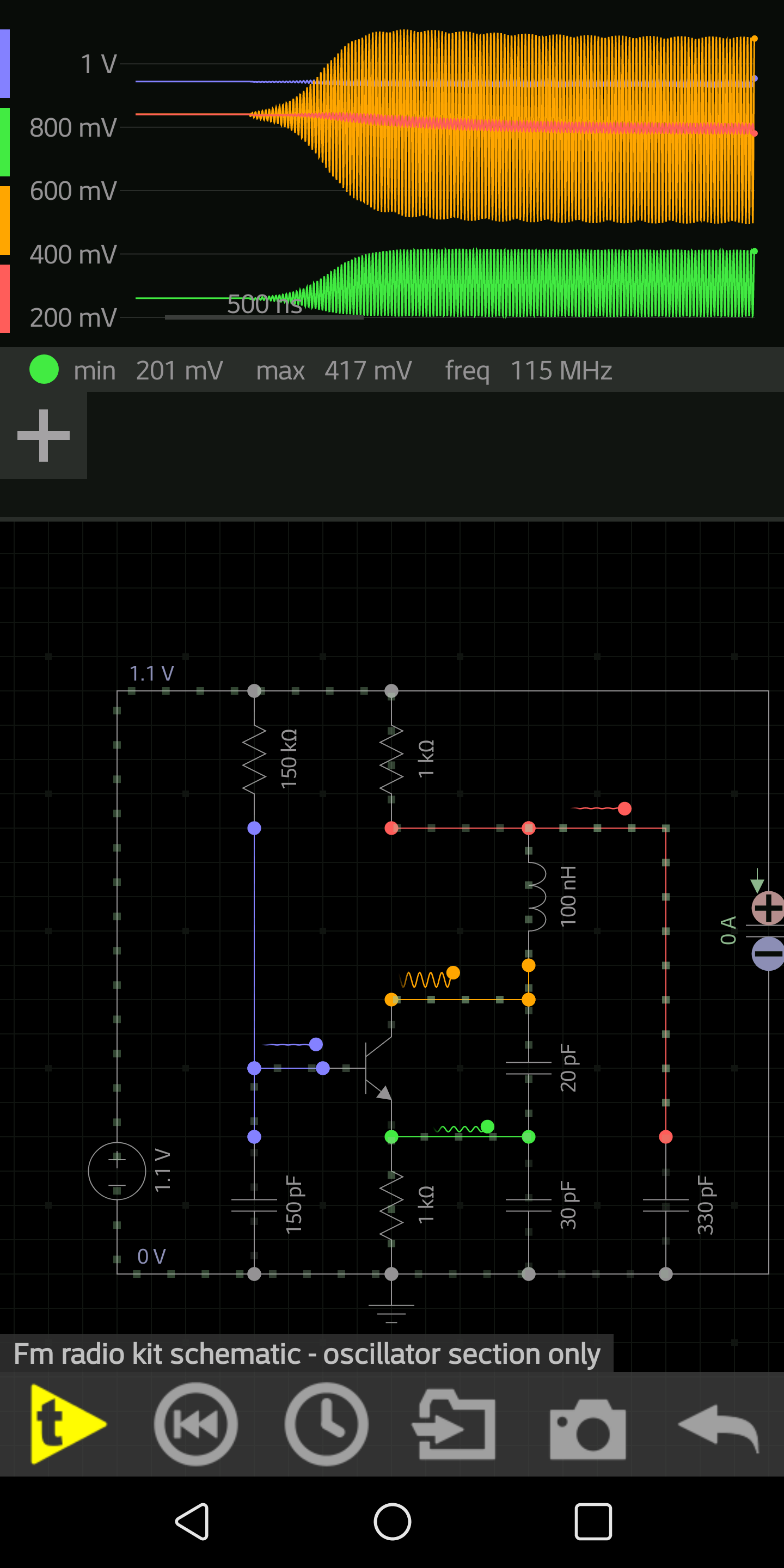
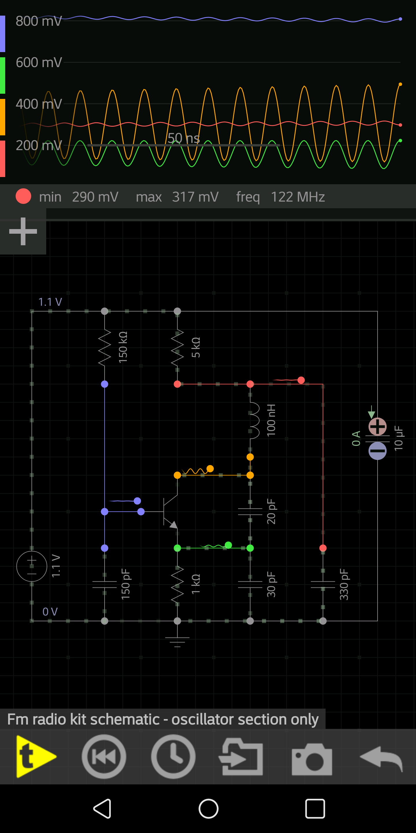
Simulation 2Simulation resultsI have built an FM radio receiver from a kit. I'm very happy with the results! It is the Sinclair Micro FM.

My goal is to learn about discrete electronics (NO IC's.)

The radio works great, but I am having trouble understanding the very first stage: Q1.

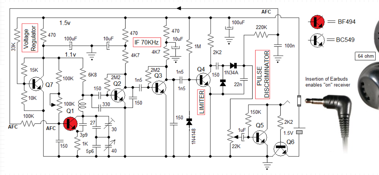
Q1 and it's supporting components act as an RF (LO) oscillator, as well as an antenna and "RF pre-amp", as well as a mixer (to multiply the incoming RF and the LO to get the IF.) If there was a separate RF pre-amp, a separate LO, and a separate mixer, I think I would understand this better. But I like the idea of using fewer components (and NO IC's) so I hope someone can assist me.

I have attached the original version of the schematic, Original schematic
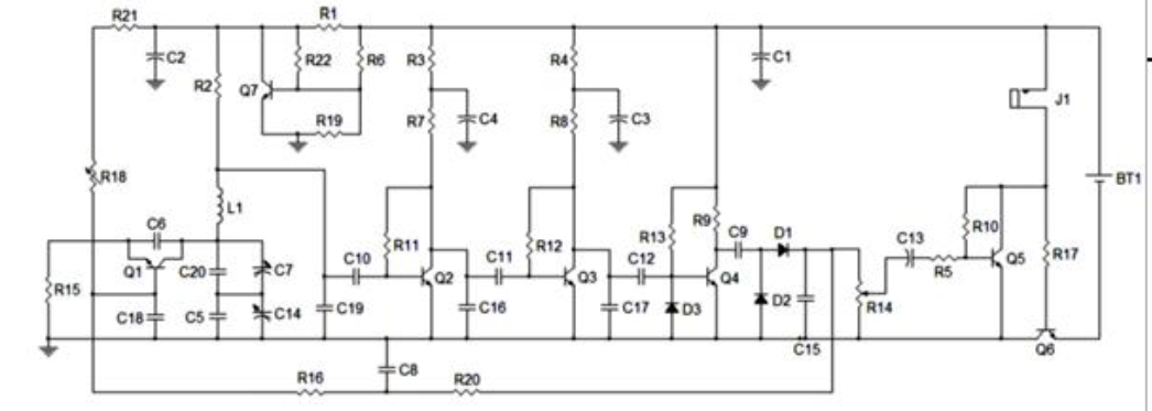
And a redrawn version: Redrawn schematic

If I am doing my calculations correctly, it seems the collector of Q1 will sit at about 0.2v DC, the base at about 0.8v DC, and the emitter at about 0.1v DC. If this is correct, then the base/collector junction is forward biased. Again, if this is correct, I don't see how Q1 will amplify transient noise to begin and sustain oscillation. I also don't see how it can amplify incoming RF.

The only thought I can come up with is... incoming RF and transient noise should show up at the collector. This will affect the base to collector voltage. As the base collector junction is FORWARD biased, a small voltage change across this junction will induce an exponential current change. I am guessing this current change, maybe through the feedback capacitor from the collector to emitter, will act with regeneration and magnify the original voltage change at the collector? This seems unconventional, but I really want to understand how this circuit oscillates! When I run this circuit in a simulator, it indeed does oscillate!

Further, I am trying to understand how this circuit mixes the incoming RF with the LO. For this to happen, the two signals need to go though a non-linear circuit. At first I was told by the designer this circuit will run near cutoff. But I see this running in "saturation". Any ideas to clear this up for me?

Lastly, why is the resistor above the coil 8.6k? Is this the best value to extract the IF (about 100k)?

Thanks so much!

In response to TimWescot, Thank you Tim. If R2 was not in the picture, I understand how the common base configuration, with positive feedback, in it's active region, oscillations start and build and become self limiting. But R2 throws me off. I know it's to extract the IM (100Khz), but placing it there seems to lower the saturation current, putting the transistor into "saturation" - the base/collector junction is forward biased. All I can imagine is a small voltage increase at the collector, from thermal noise, lessens the forward bias, and the small voltage increase is passed down to the emitter (reduced), and is inversely reciprocated back to the base, reducing the forward bias on the base/collector even more, thus increasing the collector voltage even more. I see regeneration until the base/collector comes out of saturation, into active mode, limiting the growth. Am I (way) off base?

\$\endgroup\$
2
  • \$\begingroup\$ Have you actually measured the voltages at Q1, or are you going by calculations? As long as the collector is not very forward biased it'll still have a higher impedance than the emitter, and the stage will still show some gain. Or, the thing always starts oscillating from the turn-on transient, and never needs to come up from "powered all the way on but not oscillating". \$\endgroup\$
    – TimWescott
    Commented Aug 22, 2019 at 0:56
  • \$\begingroup\$ Thanks. I measured it slightly higher than .2 at the collector... at .4v dc. So perhaps it is not as forward biased as my calculations and simulations show. I am not sure what would affect the DC voltage - I have played with various resistances and betas in the simulations - and I can't get much higher than .3v DC at the collector! I fully understand the turn-on transient, and without R2 I fully understand how the transient grows and is then finally limited. I'm just having difficultly seeing how this circuit (with R2 in place) actually amplifies when both junctions are forward biased! \$\endgroup\$
    – dhrovner
    Commented Aug 22, 2019 at 1:18

2 Answers 2

1
\$\begingroup\$

Converter stages like that act like mixers because the oscillation is strong enough that Q1 is behaving in a strongly nonlinear manner. Ideally, Q1 is operating in class A1, B or C, and only amplifying RF when it is on. That makes it into a mixer and, if the component values are chosen correctly, it will be a mixer with at least some gain.

\$\endgroup\$
10
  • \$\begingroup\$ Thank you Tim. I added to my question above as I could not fit it here! \$\endgroup\$
    – dhrovner
    Commented Aug 22, 2019 at 0:45
  • \$\begingroup\$ Doesn't class C require the transistor to go into and out of cut-off? I don't see that happening. Unless going in and out of saturation will also accomplish class C operation? But in any case I don't yet see how this circuit is amplifying the transient noise to the point of Q1 cutoff nor getting out of saturation (if indeed it is in saturation) and into the active region for a short time. Thanks for your patience with me! \$\endgroup\$
    – dhrovner
    Commented Aug 22, 2019 at 1:41
  • \$\begingroup\$ Yes, class C implies that the transistor is going into cutoff -- but that's a likely thing to happen in an oscillator. Oscillation grows until something in the circuit acts to reduce the gain of the active element. In the case of a circuit like that, usually what happens is that the base capacitor gets "pumped down" from injected base current, and holds the base at a lower voltage than it would be in linear operation. That reduces the conduction angle of the amplifier, making it class C (or B, which would have the same effect -- I'm editing my answer). \$\endgroup\$
    – TimWescott
    Commented Aug 22, 2019 at 15:09
  • \$\begingroup\$ Sadly when I simulate the autodyne stage (Q1), it indeed amplifies and oscillates and stabilizes as expected, however, I don't see Q1 going into cutoff. I see the opposite... hovering around saturation. So either something is unique about this circuit, or, I am not simulating the circuit correctly. When actually fabricated this circuit works and picks up many FM stations, so I am now just trying to understand the schematic and logic and electronics behind the working circuit. I am sure you can tell I am a novice, perhaps not knowing how to explain myself well... But thank you so much! \$\endgroup\$
    – dhrovner
    Commented Aug 22, 2019 at 15:21
  • \$\begingroup\$ It could be that the transistor is, indeed, going into saturation rather than cutoff. That would have the effect of varying the gain within a cycle, which is what's necessary for mixing. Having the transistor saturate in an oscillator circuit like that tends to kill the Q of the resonator, which significantly reduces the radio performance, but things ought to still work. \$\endgroup\$
    – TimWescott
    Commented Aug 22, 2019 at 15:45
0
\$\begingroup\$

The circuit above is in fact the Armstrong microFm kit, not the Sinclair micro Fm

I am the designer of this kit, which I have now re-introduced and you can see the kit in detail on armstorngradio.com which includes a video on the construction.

The unorthodox part of the circuit is that the inductor is also the antenna of the receiver, similar to what a ferrite rod is for MW

There is no RF amplifier and the first transistor acts as a mixer-oscillator which operates in the non-linear mode. Please note the low supply voltage of 1.1v which with the biasing makes the transistor operate in the non-linear region. The coil inherently will have the necessary incoming signal mixed with the oscilator output. Hope this helps

\$\endgroup\$

Your Answer

By clicking “Post Your Answer”, you agree to our terms of service and acknowledge you have read our privacy policy.

Not the answer you're looking for? Browse other questions tagged or ask your own question.