1
\$\begingroup\$

I made a PCB with two Arduino Pro Micro 5V on it as a control system for a machine. The PCB is powered by a 24VDC PSU and a part of that 24 VDC goes to a R-78C12-1.0 DC-DC converter. That gives 12VDC 1A to the RAW pin of the pro micro.

It worked perfectly for few weeks but one day the Arduinos randomly fried itself when I powered the machine/PSU on. The voltage regulator was the part that was damaged. I couldn’t figure out what caused it.

I used a spare PCB and since the second Arduino isn’t important/needed for now, I only used the one Arduino. I also placed a polarized capacitor between the 12VDC DC-DC Converter and GND. I did this thinking it will stabilize the 12 VDC going into the RAW pin. Now when I turn it on it works sometimes, other times the HR-SC04 Sensor and LCD screen don’t work and I noticed the VCC pin on the Arduino dropped to 2.8V. When it was having this problem, I tried to connect a micro-USB cable in and that caused the Arduino to fry again. It was the voltage regulator again that was burned and blackened.

I looked online to see if others had similar problem and couldn’t get an answer. The only option I can see right now is to get a DC-DC Converter that output 6.5V instead of 12. Attached a screenshot of the schematics I’ve drawn on the easyEDA software.

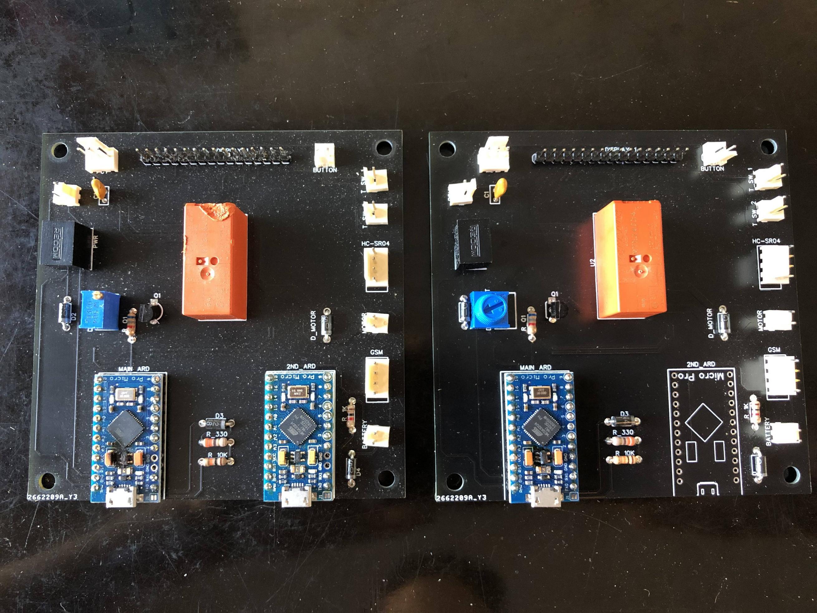
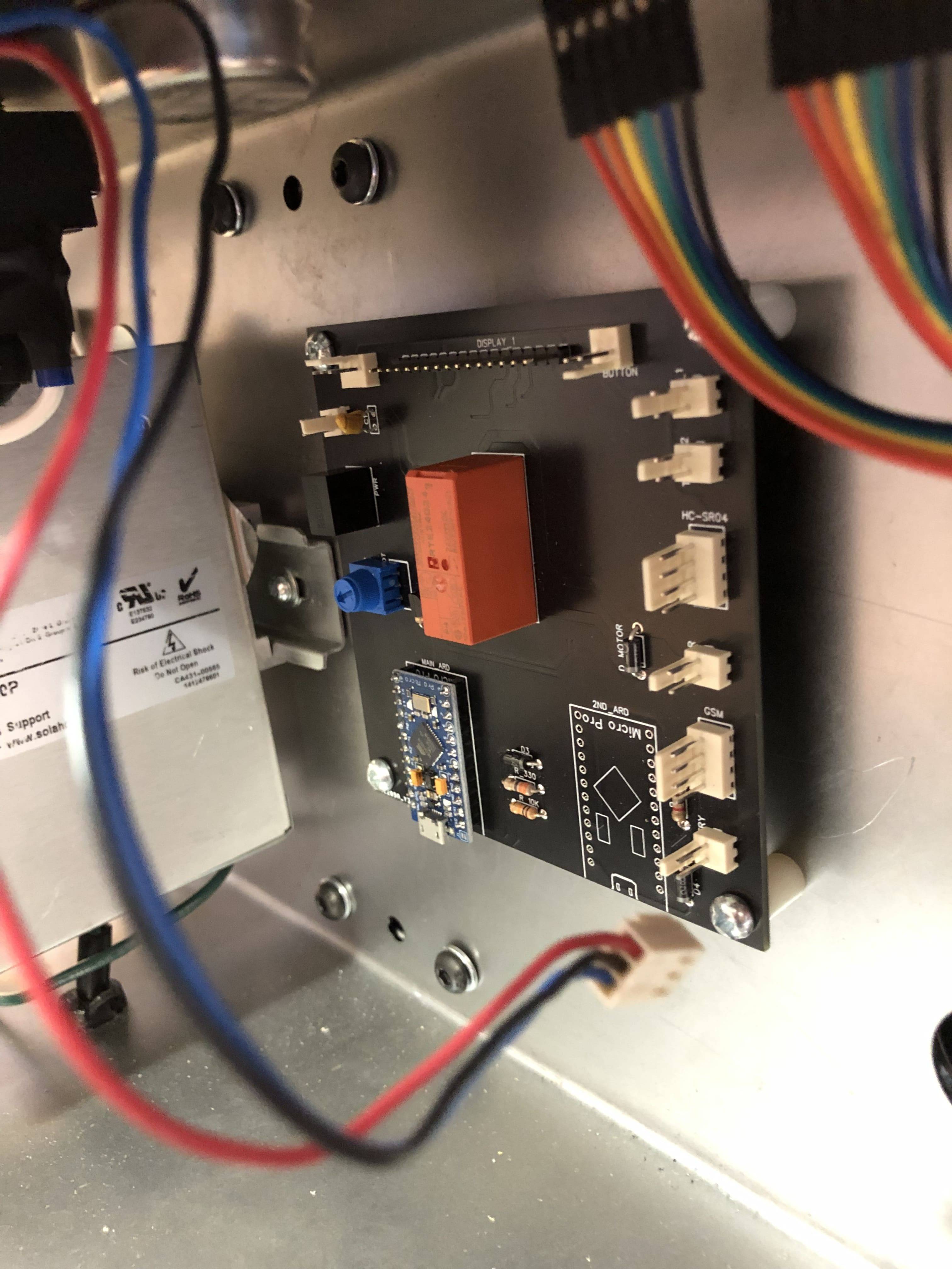
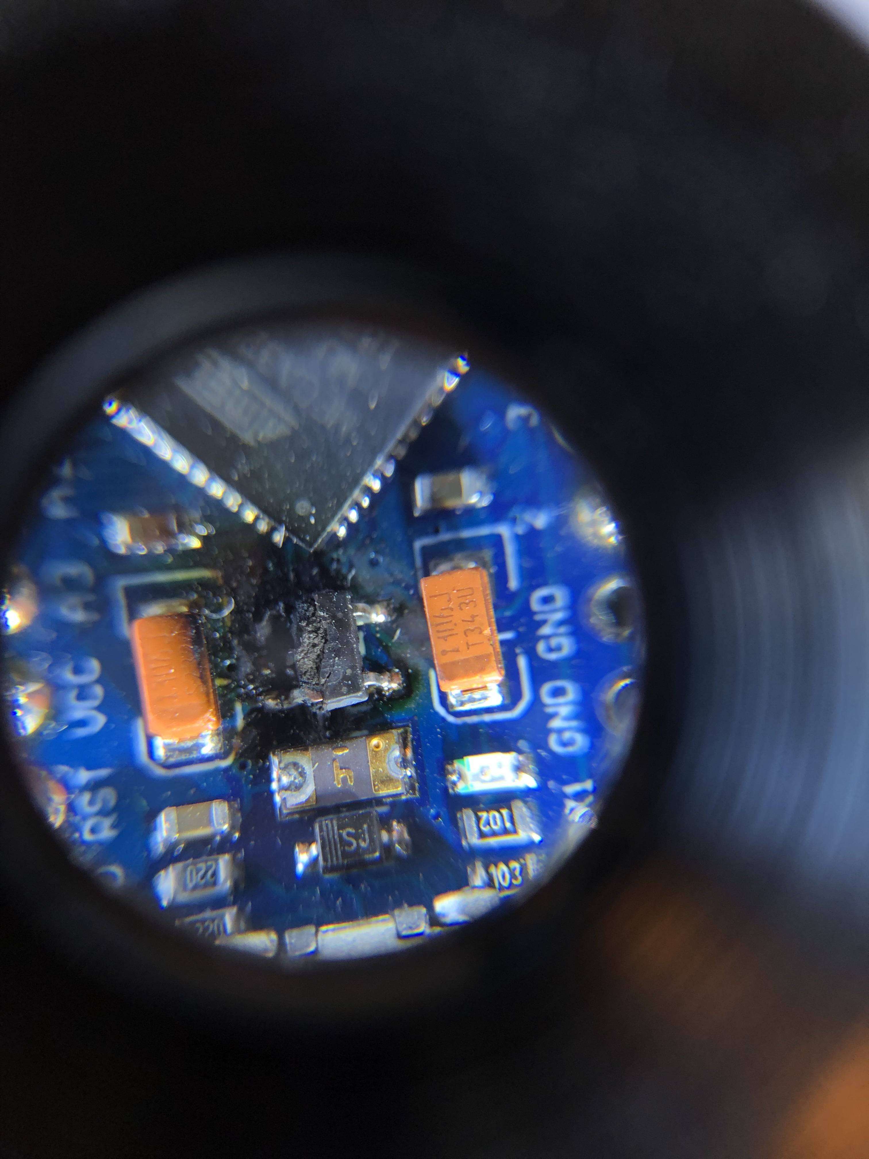
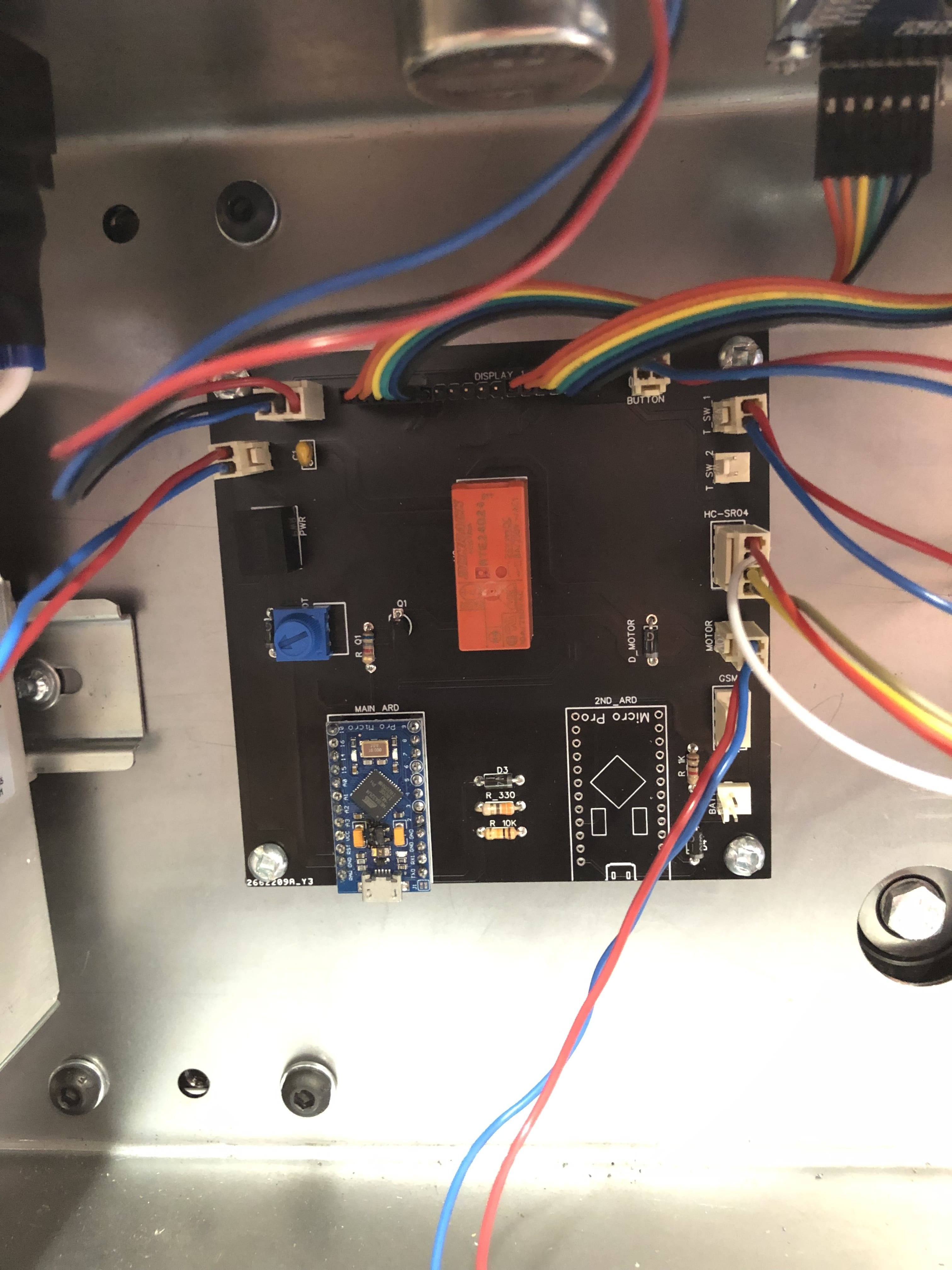
Would anyone have any idea what caused this fry up? enter image description here Schematic of the PCB enter image description here The PCB where the Arduino Pro Micros burned out enter image description here Close up of the voltage regulator. It says "4BMD" on it before it was blackened. enter image description here enter image description here The PCB mounted on the machine.There is plastic spacers so there isn't electrical contact between the sheet metal and the PCB.
\$\endgroup\$
6
  • 4
    \$\begingroup\$ Perhaps a flyback diode would be beneficial for the relay. \$\endgroup\$
    – Steve
    Commented Sep 24, 2019 at 22:38
  • \$\begingroup\$ Was there a motor plugged into the motor plug? I assume D_motor is a flyback diode on motor. \$\endgroup\$ Commented Sep 24, 2019 at 22:51
  • \$\begingroup\$ Okay. I didn't know I had to press <Enter> twice to put a space. I was wondering why I can't enter a new line before. I'll keep it in mind now. Yes the D_motor is a flyback diode for the motor. I tried to attach photos of the actual PCB as well but the file size is above the 2MB limit. Once I get it reduced, I'll show it. \$\endgroup\$
    – Agriculex
    Commented Sep 25, 2019 at 12:51
  • \$\begingroup\$ I've edited it and attached more photos of the actual PCB. \$\endgroup\$
    – Agriculex
    Commented Sep 25, 2019 at 13:14
  • \$\begingroup\$ It looks like you're powering other components from the Micro's VCC pins (which are supplied by the Micro's voltage regulator). What are those components and how much current do they draw? \$\endgroup\$
    – marcelm
    Commented Oct 7, 2019 at 13:30

3 Answers 3

6
\$\begingroup\$

The Torex XC6204 LDO regulator (markings '4BMD') is rated for 150 mA at 10 V max. Recommend 6 V ~ 9 V usage.

Updated (information overload ahead):

The 'Pro Micro' is a SparkFun design, as far as I know at least, but the boards you are using are clones. The perils of Open Hardware.

PDF of the SparkFun product, and schematic can be found here:
https://www.sparkfun.com/products/12640#documents-tab

The GitHub:
https://github.com/sparkfun/Pro_Micro

The genuine SparkFun boards use a Microchip MIC5219 regulator in the current revision, with an absolute max of 20 V, and 500 mA. Those parts can be run continuously at 12 V.

I don't remember where (schematic?) but I found a revision note reference to a 400 mA part that was likely in the original design (there were two previous revisions), that has since been upgraded by SparkFun.

Notice that the poly-fuse on the boards is also marked '4' for 400 mA, likely for an older revision board, and way too high for the Torex XC6204!

The regulator on the clone boards are not necessarily Torex XC6204, but may be clones themselves of the Torex part, or a similar related part. The last marking character 'D' is supposed to be the production batch, so I would expect it to change, but it doesn't seem to.

My Google-fu is strong, and I can be relentless. I recently purchased 10 similar boards for under $1 each, and did my research before applying power. I found a listing on an auction site 'yoycart' (new to me) for reels of the Torex XC6204 parts when I searched for 'regulator 4bmd'.

I knew someone would mention the absolute max of the Torex XC6204 part being 12 V, but yes, you don't want to run at that continuously; it's like driving with the accelerator-pedal always on the floor! You must account for power supply ripple, as well as thermal derating margin, especially with an enclosure. Hence the datasheet indicates 10 V max usage, and I recommended 9 V.

Note that the 3.3 V boards should have an 8 MHz crystal, and the 5 V boards a 16 MHz crystal. Running at 16 MHz at 3.3 V is out-of-spec for the ATmega32U4.

\$\endgroup\$
2
  • \$\begingroup\$ I believe this is the correct answer. Absolute maximum rating 12V though, but obviously it won't be healthy to maintain that voltage for longer periods. \$\endgroup\$
    – Lundin
    Commented Oct 7, 2019 at 8:12
  • \$\begingroup\$ I see. I thought it had something to do with the regulator. How did you know it was the "Torex XC6204 LDO"? I googled "4BMD Regulator" and it didn't show me anything like that. \$\endgroup\$
    – Agriculex
    Commented Oct 8, 2019 at 13:05
2
\$\begingroup\$

Several problems:

  • As noted in another answer, the regulator XC604 on these modules is rated to maximum 10V. You cannot supply it with 12V. This can be fixed by swapping out R-78C12-1.0 for the 9V equivalent, R-78C9.0-1.0.

  • Consider adding EMC filter as advised by the R-78 datasheet. At a bare minimum, you'll at least want some 10uF cap on the 24V, instead of the 1uF currently placed there.

  • You should add a flyback diode across the relay coil. Neither the transistor nor the DC/DC will like the reverse spikes. Use a TVS (rated somewhere around 30-33V) or similar fast diode. You could use the same one on the 24V input as well.

Also consider adding small series resistors towards buttons and connectors, to avoid ESD damage. Never fun to troubleshoot such problems.

\$\endgroup\$
1
  • \$\begingroup\$ Okay. Thanks for your feedback! \$\endgroup\$
    – Agriculex
    Commented Oct 8, 2019 at 13:05
1
\$\begingroup\$

I suspect you were using knock-off Arduino Pro Micro modules. The regulator on those are often marginal compared to authentic parts and will sometimes go up in smoke around 12V. You might be able to replace the regulator with a genuine part from the BOM and have no trouble. You may also put a diode in line with the 12V input to bring that voltage down a bit and protect against reverse power. Or just buy genuine assemblies from the OEM and save yourself a bit of time and frustration.

\$\endgroup\$
1
  • \$\begingroup\$ I'm suspecting that as well. I've edited the original post to include pictures of the PCB, the Arduino, and it's fried up voltage regulator. I believe the Pro Micro is made by SparkFun so the ones from them with the red PCB should be the genuine ones. I did notice the voltage regulator on the SparkFun ones had a different printing than the ones that were fried up. "M347" vs "4BMD". \$\endgroup\$
    – Agriculex
    Commented Sep 25, 2019 at 13:23

Your Answer

By clicking “Post Your Answer”, you agree to our terms of service and acknowledge you have read our privacy policy.

Not the answer you're looking for? Browse other questions tagged or ask your own question.