0
\$\begingroup\$

I am extremely fresh with this stuff (just started tinkering with my first project last week and fried one Arduino already)

Question 1:

I am basically supplying power to the Arduino from the back of my car's rear view mirror. The car's rear view mirror has 12v + ground out. I hooked that up to the Arduino RAW + GND and it fried right away! Reading the docs and MANY other posts before trying this, the RAW pin can take up to 12V and uses the built-in 5V regulator. Apparently, not in my case! What did I do wrong?

Question 2

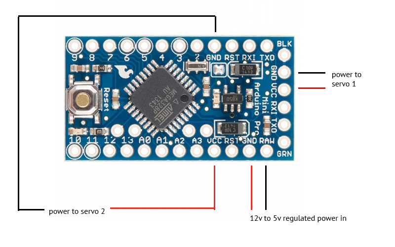
I basically need to power 2 servos and trying to not splice any wires. If I use the car's back view mirror to a 5v regulator then to the Arduino, can I hook up to the RAW still and use the other two VCC pins to supply power to 2 servos? I know the bottom VCC in the picture below does power out, but not sure about the VCC on the right if it outputs power too or is just an intake to power the Arduino itself.

If I have regulated 12v to 5v source, can I still connect that to RAW?

enter image description here

\$\endgroup\$
2
  • 1
    \$\begingroup\$ Try to search a schematic for your board and see how the RAW pin is connected. \$\endgroup\$ Commented Aug 8, 2016 at 2:48
  • \$\begingroup\$ Welcome to EE.SE! Remember that a car's "12V" isn't really 12VDC. With the car alternator running, it's 13.8-14.5V and can be distinctly higher or lower, including sudden spikes/dips, depending on operating circumstances. Automotive power supplies aren't simple things to do properly. Additionally, it would probably be more reliable to power the servos from your 5V regulator. Wiring harnesses are indeed part of electronics design. \$\endgroup\$ Commented Aug 8, 2016 at 2:50

2 Answers 2

0
\$\begingroup\$

It fried because of one of three reasons.

  1. You miswired it or a solder bridge or short. Your diagram has the red wire going to ground and black to raw. Red is normally positive. That alone suggests a miswire.

  2. It's a bad board or clone or bad part.

  3. You are pushing the 5V regulator too much. A car 12V system is really up to 14.5V, and sometime spikes higher. And depending on your load, a linear regulator can burn itself out. It's onboard regulator can only do 150mA.

Not sure about what your servo specs are. If they run at 5V, that's fine. Both VCC pins are connected together, they are the same net. The onboard 5V regulator can only do 150mA, so the servos would draw too much. Use a Car USB adapter connected to VCC. They are 12V to 5V regulators and most do 600mA and above.

\$\endgroup\$
6
  • \$\begingroup\$ Got it! So for my diagram, is it ok to supply regulated power to the RAW pin and use two servos from both VCC's? or not two servos, but two powered devices from both VCC's? Is that technically possible? \$\endgroup\$ Commented Aug 8, 2016 at 3:11
  • \$\begingroup\$ As for the red/black wires mistake in my diagram, it is just a simple photoshop mistake. \$\endgroup\$ Commented Aug 8, 2016 at 3:14
  • \$\begingroup\$ @hyperexpert yes, you can use the VCC pins as power output. No, you normally can't connect 5V in to the RAW pin, due to the regulator's minimum input voltage (It's dropout voltage). \$\endgroup\$
    – Passerby
    Commented Aug 8, 2016 at 3:14
  • \$\begingroup\$ Ok! so in this case, I will need to connect one of the servos to external power. Which is what I wanted to avoid to make the setup more "portable" \$\endgroup\$ Commented Aug 8, 2016 at 3:19
  • \$\begingroup\$ @hyperexpert why? Just solder the two servos to the same pin or "splice the wires". That's the simplest solution... \$\endgroup\$
    – Passerby
    Commented Aug 8, 2016 at 3:47
0
\$\begingroup\$

Here's an answer to Q1, I'll see if I can add in on Q2 later:

Car power is normally very noisy. While it says 12V, remember that this is 12V from the batteries: it's not 12V any more than an alkaline battery is 1.5V. Likely your battery was fully charged, and then your 12V lead-acid battery has a voltage of over 13V. If a regulator has an absolute maximum input voltage of 12V, it means 12V. Go over that, for even a moment, and it will explode.

Also, the line probably has a ton of noise on it: there could be spikes of 15V or more on that line, and it only takes an instant of overvoltage to fry your MCU.

There's a reason why automotive specs are so demanding...

For Q2: do not attempt this! Look at how much current a servo draws, and compare that with how much the regulator can put out. Overcurrent = fried regulator.

\$\endgroup\$
2
  • \$\begingroup\$ For Q2, what if not both servos will be operating at the same time? Also, will it still be possible if lets say a servo and an LED were connected instead of two servos? I basically want to understand if my diagram is technically correct \$\endgroup\$ Commented Aug 8, 2016 at 3:09
  • \$\begingroup\$ @hyperexpert NO! Like I said, look at how much current 1 servo draws, and compare it to your limit. If I'm not very much mistaken, it will be over by a lot. However, LED's are fine. \$\endgroup\$
    – dpdt
    Commented Aug 8, 2016 at 22:56

Your Answer

By clicking “Post Your Answer”, you agree to our terms of service and acknowledge you have read our privacy policy.

Not the answer you're looking for? Browse other questions tagged or ask your own question.