0
\$\begingroup\$

I'm trying to improve the accuracy of the ADC by amplifying the signal by 1/256 (i.e. 1/2^8) to make 2 8-bit ADC into 16-bit ADC. My question is can the ADC give good results if the ADC values are from +25uV to -25uV by putting the reference voltage at 50uV.

I'm using ATxmega256A3U. I know that if the microcontroller says 0 to 2.5V then it should be good but I'm worried/curious if this will work. Has anyone tried it before?

\$\endgroup\$
16
  • 3
    \$\begingroup\$ Um, you're not converting an 8-bit ADC into an 16-bit ADC by amplifying the input signal. The only thing you might be achieving is better using the actual dynamic range to actually get close to the original 8-bit if your amplitude range was too low or too high before. And what does amplifying the signal have to do with using a specific, very low, reference voltage (that won't work, honestly, for noise reasons). \$\endgroup\$ Commented Nov 20, 2019 at 21:10
  • 4
    \$\begingroup\$ I think you have multiple misconceptions, and I don't know what you've got wrong. Could you describe the signal you're trying to measure in detail? \$\endgroup\$ Commented Nov 20, 2019 at 21:12
  • 2
    \$\begingroup\$ Perhaps describe the signal as @MarcusMüller asks, and also show us a schematic of what you're planning? I suspect that the real answer is that you need to use a 16-bit ADC, and possibly a properly-configured amplifier. \$\endgroup\$
    – TimWescott
    Commented Nov 20, 2019 at 22:07
  • 2
    \$\begingroup\$ that "somehow by amplifying" doesn't work like that; you really need to extend your question to describe all this in detail! How should we have read that from your original question! \$\endgroup\$ Commented Nov 20, 2019 at 22:59
  • 4
    \$\begingroup\$ @neerajb no. I swear that won't work, at all. You're so far off... your "can I scale down the reference voltage to 50 µV" indicates you have not even thought about thermal noise. If you don't do that, I can guarantee that your experiment won't yield anything worth 32 bit of information (that's mathematically provable). I don't care the least for your confidentiality constraints: If you can't describe the problem you want to solve, we can't help you. and you're clearly in no position to measure successfully. \$\endgroup\$ Commented Nov 20, 2019 at 23:47

2 Answers 2

2
\$\begingroup\$

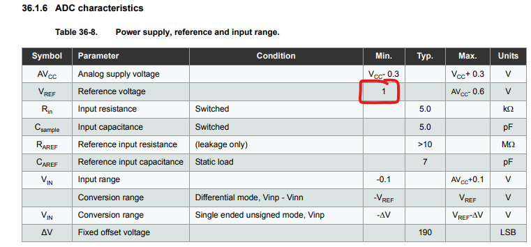
For the first ATxmega256 part I found a datasheet for, this will be out of spec:

enter image description here

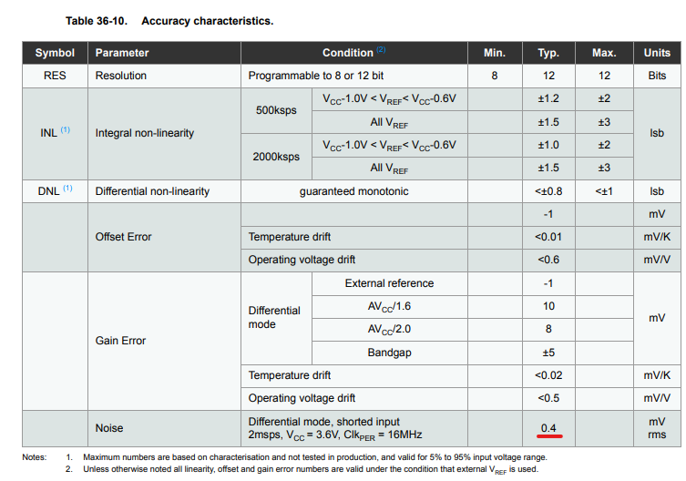
Also be aware that 50 uV (never mind 50 uV / 256) is below the noise floor for this ADC:

enter image description here

\$\endgroup\$
6
  • \$\begingroup\$ And half of the input range won't sensibly be quantized, if OP's input voltage range is actually symmetric around 0V... \$\endgroup\$ Commented Nov 20, 2019 at 21:12
  • \$\begingroup\$ @MarcusMüller, and never mind that the noise floor is probably above 50 uV, and ... \$\endgroup\$
    – The Photon
    Commented Nov 20, 2019 at 21:14
  • \$\begingroup\$ The minimum reference voltage should be 1V. That means I won't be able to improve the resolution by lowering the reference. I guess that answers my question. \$\endgroup\$
    – neerajb
    Commented Nov 20, 2019 at 21:43
  • \$\begingroup\$ @neerajb Really, describe what you're trying to do: You don't get better measurement resolution by making your measurement device worse, but by increasing the signal amplitude, you really have some misconceptions. I bet some of the challenges you face are easy to solve, but you just leave us in the dark. Don't do that! \$\endgroup\$ Commented Nov 20, 2019 at 21:57
  • 1
    \$\begingroup\$ With such poor linearity, there is no value in trying to cascade these ADCs. The INL and DNL are just barely adequate for a cheap 12-bit SAR ADC. You’re better off buying an external delta-sigma ADC to get high 24-bit resolution with appropriate dynamic range for the signal you want to measure. Many delta-sigma ADC are available with internal PGA (amplifier), which is more likely what you actually need. \$\endgroup\$
    – MarkU
    Commented Nov 21, 2019 at 0:36
0
\$\begingroup\$

What is needed to achieve 1 nanoVolt RMS noise, in a sampled-capacitor system?

We will use the formula Vnoise_rms = sqrt( K * T / C)

and K = Boltzmann Constant, T is Kelvin Temperature and C is the capacitance.

For 290 degree Kelvin (17 C) and 10 picoFarad, the formula spits out

Vnoise_rms = 20 microVolts RMS

We want to reduce that noise to 1nanoVolt.

But first, how about we compute what is needed for 1 microvolt RMS, which many 24-bit ADCs approach.

For 1 uV, we need to increase the C by 20*20 or 400X, to 4,000 picoFarad. Thus in an oversampled 24-bit ADC, you will notice plenty of charge being demanded from the sensor.

Suppose you have 5 volts from the sensor. How much energy/power is needed?

Energy_Cap = 0.5 * C * V * V, = 0.5 * 4nanoFarad * 5 * 5 = 2nF * 25 = 50 nanoJoule, for 24 bit ADC --------at a minimum, per conversion, for 1uV RMS noise. Ignoring the internal comparators and opamps, and any VREF noise and VDD noise. And ignoring any EFI coupling thru the plastic surrounding the silicon, and ignoring any HFI (magnetic coupling) onto the silicon or onto Vin+ and Vin- and Vref.

OK Now for the original question ---- 1 nanoVolt.

The capacitor must be 1000 * 1,000 larger, at 0.004 Farad.

The energy must be 1,000 * 1,000 larger, at 50 millijoule, per conversion.

What does the math tell us? for 40,000 conversion/second, we need 0.05joule * 40,000 or we need 2,000 watts signal power into the 32-bir ADC.

And the ADC, in generating the 32 bits, converts the 2,000 watts into heat.

\$\endgroup\$

Your Answer

By clicking “Post Your Answer”, you agree to our terms of service and acknowledge you have read our privacy policy.

Not the answer you're looking for? Browse other questions tagged or ask your own question.