1
\$\begingroup\$

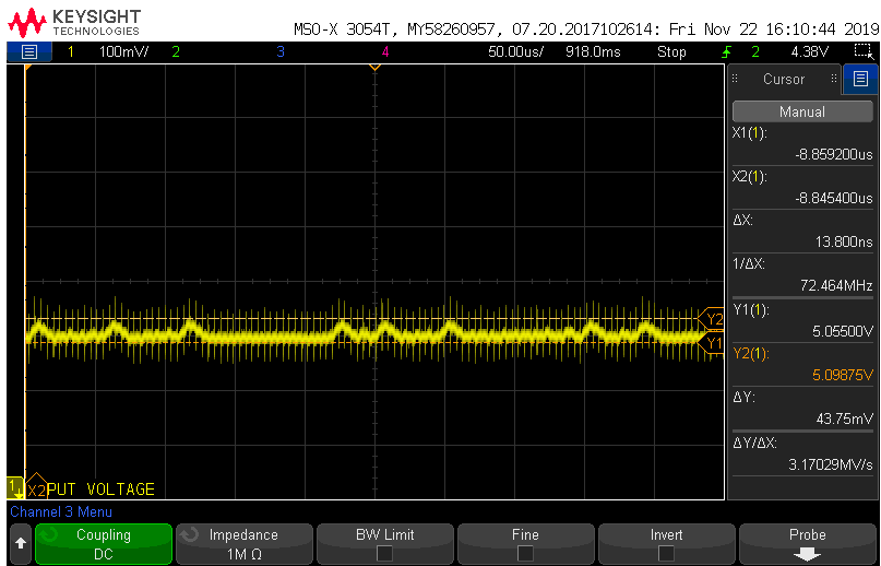
Please check the below waveform of my 5V output ripple of the buck converter.

I am measuring the output ripple across the output capacitor of the converter. Why are these spikes coming while measuring even though I am using the short spring type ground tip

Switching frequency of the converter is 248kHz. And one more thing I am observing is that, while I measure on one channel, the switching frequency at the switching node of the converter and on the other channel the ripple voltage, the ripple voltage amplitude is going high. But If I measure it separately, I am able to get the correct ripple voltage amplitude. What might the reason for this? I am using short ground tip while probing on both the channels

enter image description here

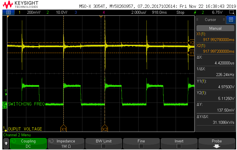
Updated Waveform, along with switching frequency. Please check the below waveform. I am probing across the output cap of buck converter with spring tip and the switching frequency at the cathode of the diode (referring common buck topology) . Can you see, when I measure both waveforms together, I am getting this awful spike which I have marked with cursors?

Why is that and what to do to get proper waveform?

enter image description here

\$\endgroup\$
5
  • \$\begingroup\$ What is the switching frequency of the converter? \$\endgroup\$ Commented Nov 22, 2019 at 8:09
  • \$\begingroup\$ Switching frequency of the converter is 248kHz. And one more thing I am observing is that, while I measure on one channel, the switching frequency at the switching node of the converter and on the other channel the ripple voltage, the ripple voltage amplitude is going high. But If I measure it separately, I am able to get the correct ripple voltage amplitude. What might the reason for this? I am using short ground tip while probing on both the channels \$\endgroup\$
    – user220456
    Commented Nov 22, 2019 at 8:12
  • \$\begingroup\$ Notice the frequency of these ripples is around 230kHz. It looks like ripples coming from converter switching. Maybe the RC values of the design are too low. It also might be the electromagnetic field coupling due to not optimized PCB layout. I would try higher inductance value coil or use additional RC filter on the output. \$\endgroup\$
    – KJA
    Commented Nov 22, 2019 at 8:20
  • \$\begingroup\$ Yes. The ripple frequency is around 226kHz. So, I should measure the peak to peak value of this for actual ripple voltage, right? \$\endgroup\$
    – user220456
    Commented Nov 22, 2019 at 8:25
  • \$\begingroup\$ I have updated my question with the waveform taken now. Please clarify \$\endgroup\$
    – user220456
    Commented Nov 22, 2019 at 8:34

1 Answer 1

2
\$\begingroup\$

measuring ... at the switching node of the converter

But If I measure it separately, I am able to get the correct ripple voltage amplitude

The switching node of the converter is very sensitive to any additional capacitance loading. Even the small capacitance of a scope probe (use a 10:1 probe to get the smallest capacitance!) is enough to influence the behavior.

You might think, well this is only 248 kHz so it's not that high in frequency. That is correct but that 248 kHz signal is not a sine wave. Ideally it's more like a square wave with very sharp edges (due to fast switching which is needed for good efficiency, low switching losses). Such a square wave has harmonic frequencies content up to very high frequencies, like up to 1 GHz or higher. At such frequencies, any additional capacitance and inductance does make a difference!

In a non-synchronous DCDC down converter there will be a Schottky diode between the switching node and ground. The capacitance of this diode influences the behavior of the converter even though this capacitance can be quite small depending on the diode that is used. When you probe the switching node you add some capacitance in parallel with this diode.

For an accurate ripple measurement, only probe at the output and probe directly across the filter capacitor at the output.

\$\endgroup\$
9
  • \$\begingroup\$ Thank you! But how does measurement influence my output capacitor ripple voltage? Are you meaning to say that by measuring the switching frequency at the switching node, I am adding more capacitance. And this additional capacitance is reflected at the output capacitor of the converter and therefore I see high Ripple voltage? \$\endgroup\$
    – user220456
    Commented Nov 22, 2019 at 8:37
  • \$\begingroup\$ Or does it have to do something with my grounding ? Nothing related to grounding? \$\endgroup\$
    – user220456
    Commented Nov 22, 2019 at 8:39
  • \$\begingroup\$ Thank you! Could you please clarify my comments? \$\endgroup\$
    – user220456
    Commented Nov 22, 2019 at 8:40
  • \$\begingroup\$ The switching node is simply very sensitive and has high frequency content. So anything you touch it with will influence the DCDC's behavior! So: just don't touch it unless you have a really-really low inductance/capacitance probe like a FET probe. A proper one will be quite expensive though. \$\endgroup\$ Commented Nov 22, 2019 at 8:40
  • 3
    \$\begingroup\$ Have you researched "DCDC converter ripple voltage" and understood what causes this ripple voltage and what it (theoretically) looks like? You have to decrease the timebase value and sensitivity to see the right waveform. please help me clearly I'm not going to "hold your hand" to guide you, I expect that you do your own research/study first. \$\endgroup\$ Commented Nov 22, 2019 at 9:24

Your Answer

By clicking “Post Your Answer”, you agree to our terms of service and acknowledge you have read our privacy policy.