3
\$\begingroup\$

I'm a mechanical engineer, who has the luck to design an easy transimpedance amplifier circuit to convert the current of a photodiode to a voltage between 0 and 5V (without really knowing anything about it.)

I used this reference design from Texas Instruments and did the calculations.

After some weired results with the voltage divider in place, I changed the design to the one you can see in the next picture.

(The values of the components are different in my design.)

enter image description here

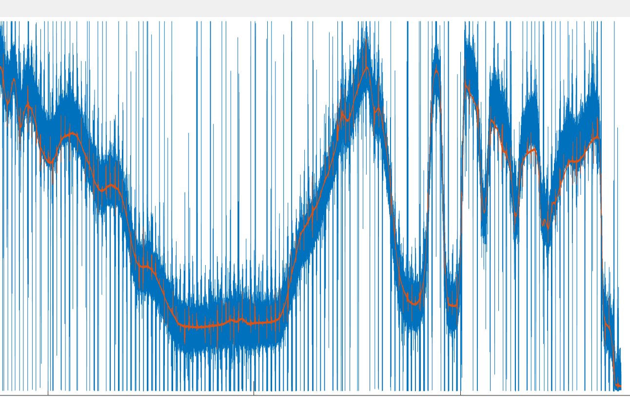
I ended up with some "useful" measurements, which showed more or less the same signal pattern compared to a professionally built transimpedance amplifier. See picture below. Blue line is my DIY-version, orange line is the bought amplifier.

As you can see, there is a lot of noise in my design. I'm not really deep into electronics so I don't know how to improve the performance.

Can somebody give me some advice how I can reduce the noise?

FYI: I used this opamp.

enter image description here

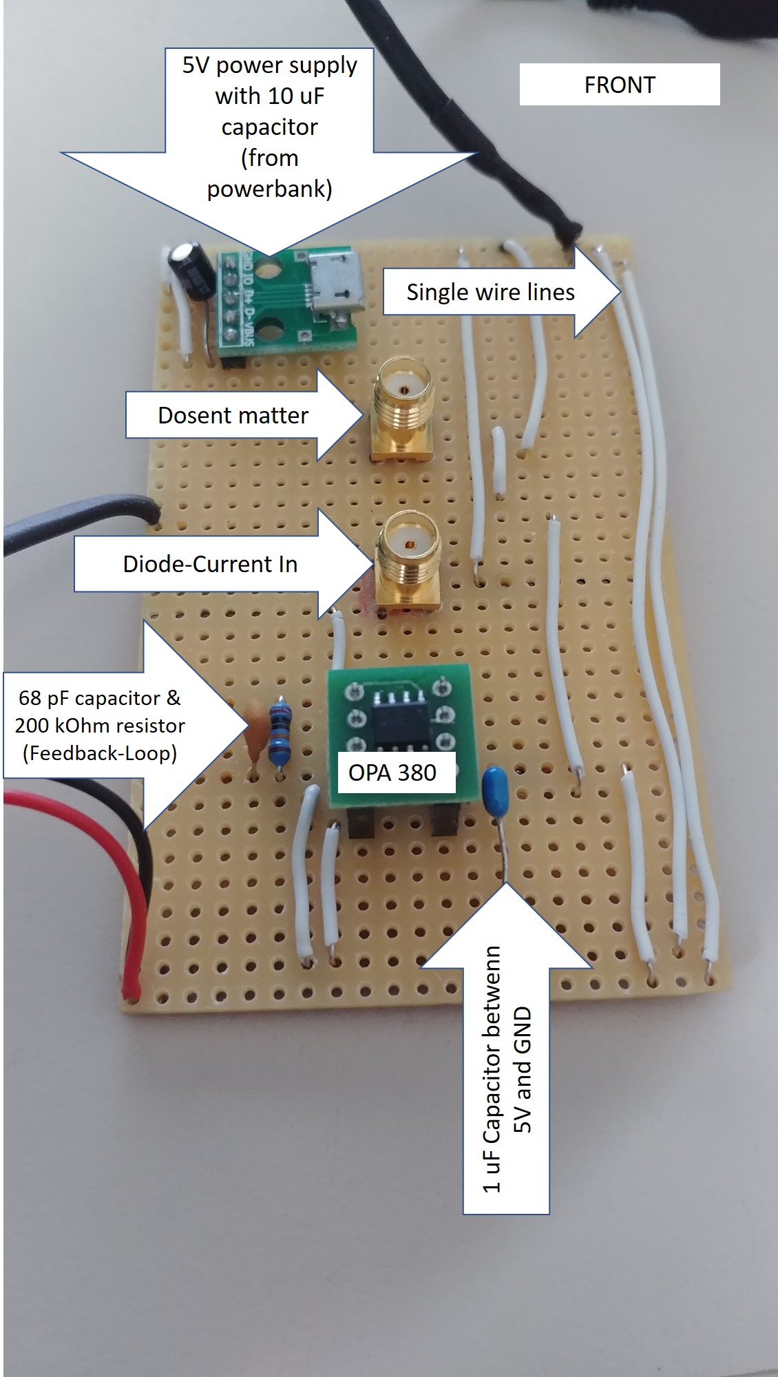
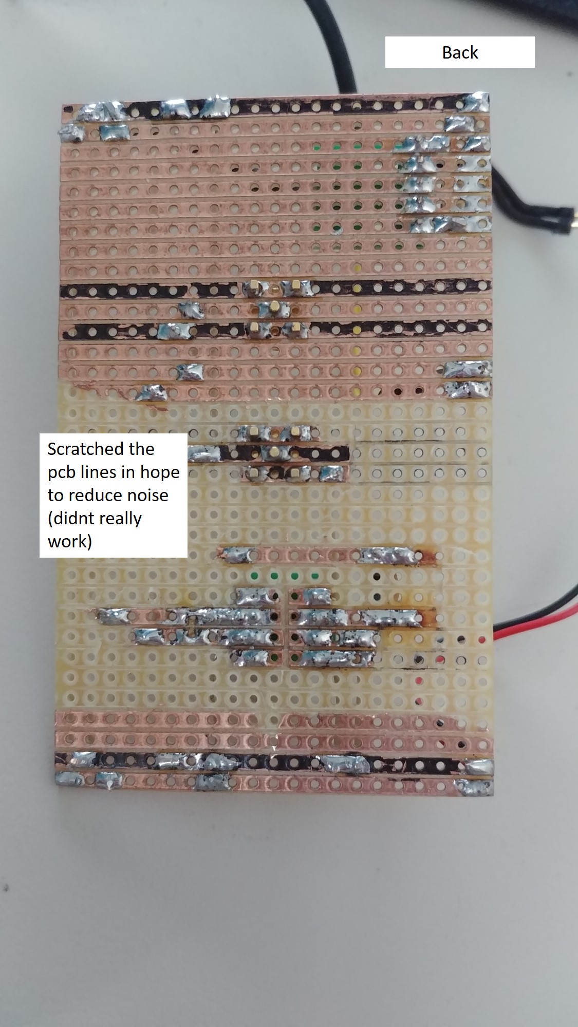
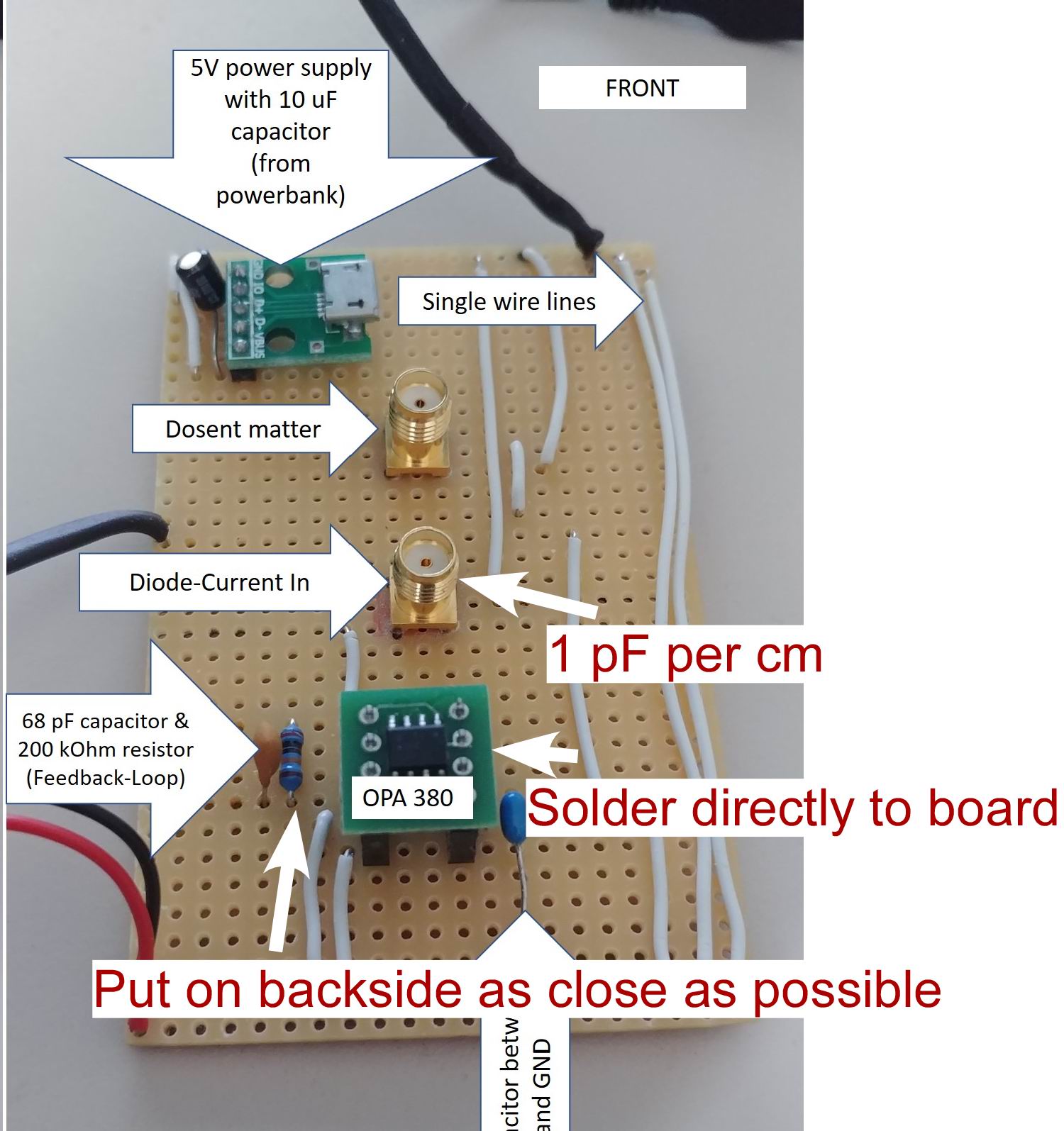
EDIT: I added the pitures of my PCB + the values of the components. When I read through the comments I realized that there is more to consider than I expected. I dont need a super low noise transimpedance amplifier, but lower noise would be great. Are there any easy fixes which I can use without additonal curcitry?

enter image description here enter image description here

\$\endgroup\$
7
  • \$\begingroup\$ That noise beats most others I’ve seen. use differential amplifier With same RC parts with STP cable and an LDO to supply supply noise then maybe an RF cap from Earth Gnd to 0V with cct over a ground plane, not a breadboard \$\endgroup\$
    – D.A.S.
    Commented Aug 30, 2020 at 15:26
  • 5
    \$\begingroup\$ Show your actual circuit with component details, power supply decoupling and specify the power supply you used and how you constructed it. \$\endgroup\$
    – Andy aka
    Commented Aug 30, 2020 at 15:56
  • \$\begingroup\$ Do you have any design specs? the very high impedances makes any conductor look like an antenna, so ground planes are needed to shunt stray noise. \$\endgroup\$
    – D.A.S.
    Commented Aug 30, 2020 at 16:10
  • \$\begingroup\$ Where are the PD datasheet link and photos of your layout with schematic? is this for DC or AC what f, sensitivity? \$\endgroup\$
    – D.A.S.
    Commented Aug 30, 2020 at 16:46
  • \$\begingroup\$ Look papers by Bonnie Baker (used to be a very sterile personality when talking with her) and Jim Todsen (used to be quite the opposite and very embracing by comparison.) Both at one time worked for Burr Brown, which produces some very nice ICs with respect this kind of application area. I'm thinking more towards papers by Bonnie Brown, though. They are pretty good, relatively easy to read and understand, and cover most of what you need to know to think for yourself. \$\endgroup\$
    – jonk
    Commented Aug 30, 2020 at 17:37

4 Answers 4

3
\$\begingroup\$

I recently went through this whole process designing some TIA boards for a few different applications where I tried prototyping like you're doing, realized it doesn't really work for these circuits, and then ordered PCBs which solved most of my problems. I'll try and give very non-technical answers and explain what I did in your situation.

Problems:

Feedback values look wrong

I don't see the photodiode you've chosen, but when I think large area photodiode, I think a few hundred pF of capacitance. Plugging in the values you've chosen into Eq 1. of the opamp datasheet (pg11) and solving for the diode capacitance, I get that you are using a 3.3 uF photodiode, or about 1 million times larger than a typical value. I think you probably mixed up a unit somewhere.

If you solve Eqn 1 for a 200pF diode, you get that the feedback capacitor should be ~2pF, which is actually less that the parasitic capacitance you have in that circuit, so you can omit the feedback capacitor entirely.

Circuit board layout suggestions

That perf board you're using is a terrible idea for circuits like this, but if you want to try, you have everything WAY too far apart. You're also using a SMA connector and (from your link above) you appear to have both amps plugged in at the same time (!). Here are some ways you can fix your design:
enter image description here

Move everything as close as possible and use both sides of the board. Try to fit everything in ~ 1 square centimeter or so if you can. Solder the decoupling cap directly to the opamp pin. If you really must use a coax cable (which you should not be using), cut it as short as possible since you're gaining ~ 1pF of capacitance per cm of cable and then factor in that capacitance into your design. To put that into perspective, the tech note you linked above compensates for a photodiode capacitance equal to 4 inches of cable, so that should suggest to you how close the amp should be to the diode. Thorlabs, who sells TIAs for photodiodes, ships them with a custom 1 inch long SMA cable and a note saying that you must use that cable as its capacitance is designed into the circuit.

Consider having a real PCB made, it costs almost nothing

Thanks to covid, you can order a stack of custom PCBs these days for ~20 USD shipped to the USA/EU and get them inside of a week. With tools like EasyEDA that partner with cheap prototyping services, you could likely design a basic circuit like this in your web browser and send it off to be fabbed in less than the time it took you to solder all that perfboard together. At these frequencies you can use 1206 components, which are simple to solder and do not require a microscope (just tweezers and a $10 chisel tip for your iron). I would strongly encourage you to look into this. You will get a vastly better performing device, and one that is probably small enough that you can just solder the photodiode to the board and mount it all in place (avoiding the coax cable).

You'll also get a stack of boards which means you can make as many TIAs as you need in the future for very little time.

Need to reverse bias the diode

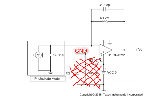
As mentioned in the other answers, you need to have a reverse bias on that diode. Either put the resistor network back into the circuit, or hook up a second negative power supply to the other end of the diode. Probably once you have more reasonable values for the feedback network and clean up your circuit layout you'll find that it works a lot better.

\$\endgroup\$
3
\$\begingroup\$

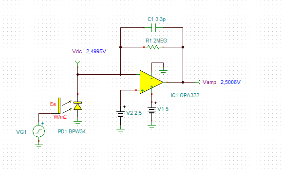
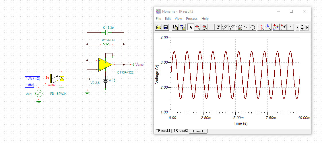
There is a much bigger mistake here than it seems at first glance. The photodiode is a current source only in the reverse direction. It does not receive a reverse voltage here, so it acts as a solar cell and a source of voltage. Plus a large surface antenna. The original circuit is better, where the diode receives some of cut-off voltage. Even better, if the reverse voltage is just half the supply voltage. This is how the dynamics can be greatest.

DC circuit without diode signal: opa322

With very small sinusoidal illumination (1uW / m2): opa322-1

\$\endgroup\$
2
\$\begingroup\$

You've not posted a link to your photodiode, or other wise defined the signal you expect from the diode so no one can check your calculations for gain. I'm going to ignore all that, because I think your difficulties are more basic. I'm going to make a couple of suggestions that you can try out easily.

  1. Biggest thing is, don't use a USB battery bank. The output of those things is noisy. Use three AA cells in series to get 4.5V, and test your circuit again. If the noise improves drastically, then you can work on getting a clean 5V source. Probably better to use a low noise linear regulator. You'll have to have a higher input voltage (maybe 7V) at the input to the regulator.
  2. Shorten the wires in your circuit. You have an amplifier with a lot of gain. Each wire acts as an antenna. The wires can pick up noise and interference from the environment, and your amplifier will happily amplify the noise along with your signal.

Removing the bias circuit (the two resistors and the capacitor you scratched out) was probably a bad idea. TI didn't put it there for giggles. If it made your noise situation worse, I think there's a fair chance it was because your power source is too noisy.

You may want to check your 5V supply before changing things. Hook it up to an oscilloscope and have a look.

\$\endgroup\$
1
\$\begingroup\$

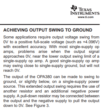
The vertical scale on your plot is missing so we don't know average output voltage. For low-light applications, output voltage will be very nearly zero volts. This is a problem with a single-polarity DC power supply. The region between 0V and 100mV is not particularly well-controlled. Read the OP380 data sheet:
clip from OP380 data sheet

Will this reduce noise? Hard to tell, since we don't know the dynamics that cause non-linearity near zero volts...Texas Instruments merely suggest "problems arise". It might help to do what the data sheet suggests.


Some builders make the mistake of running long wires between photodiode and opamp input. This path should be really short.


As with any op-amp, add a bypass capacitor from opamp's DC supply pin to opamp's ground pin (DC supply return). Value anything above a microfarad.

\$\endgroup\$

Your Answer

By clicking “Post Your Answer”, you agree to our terms of service and acknowledge you have read our privacy policy.

Not the answer you're looking for? Browse other questions tagged or ask your own question.