0
\$\begingroup\$

I am using the following fan : ME70201V1-000U-A99, which should be supplied at 12 V and consumes about 150 mA.

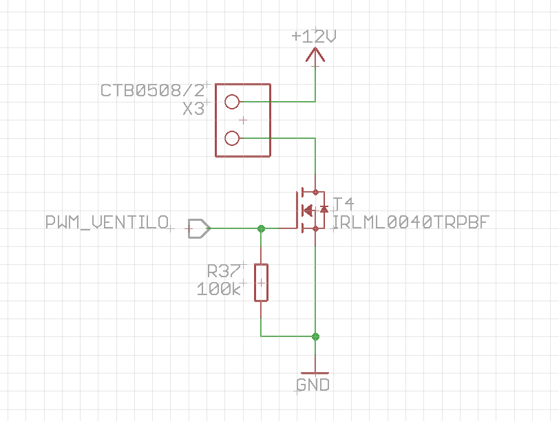
My schematics is as follows :

enter image description here

Than fan is connected to X3. PWM_VENTILO is the PWM output of a microcontroller.

If PWM_VENTILO is a simple high GPIO output, it spins at full speed. But if I try to control its speed with the PWM, it does not spin. I have tried different frequencies (some Hz to 20 kHz) and different duty cycles, I always have the same result : it gets stuck and never spins. At low frequency, it kinda works, but the spin is irregular. The MOSFET transistor accepts voltages and current which are necessary.

Is there something I am doing wrong ?

Thanks

\$\endgroup\$
5
  • 3
    \$\begingroup\$ Perhaps the "auto restart" function is preventing it from running via PWM? A lot of brushless fans will be better controlled via 4 pin PWM (which will also indicate that the are meant to be run in different speeds). In my experience a lot of these higher RPM fans aren't meant to be ran at lower speeds (won't even start at low PWM duty cycles). \$\endgroup\$
    – Wesley Lee
    Commented Oct 23, 2020 at 14:53
  • 3
    \$\begingroup\$ Do you have access to an oscilloscope? Look at the actual PWM waveform that you are creating. I strongly suspect that you do not have the PWM configured correctly. \$\endgroup\$ Commented Oct 23, 2020 at 14:55
  • 1
    \$\begingroup\$ I have checked the PWM, the one at the gate of the transistor and the one at the drain are as expected. \$\endgroup\$ Commented Oct 23, 2020 at 15:05
  • 1
    \$\begingroup\$ Adding to my previous comment: have you tried other fans? \$\endgroup\$
    – Wesley Lee
    Commented Oct 23, 2020 at 15:12
  • 1
    \$\begingroup\$ No, that's a good idea. I have another one but is it almost the same reference, it is just a little bigger. I will try to find another one and test it. \$\endgroup\$ Commented Oct 23, 2020 at 15:15

4 Answers 4

18
\$\begingroup\$

The Mouser datasheet says:

DO NOT use power or ground PWM to control the fan speed

(page 11)

This is because it's a BLDC fan which has a small onboard controller of its own. You need a PWM-able one, which may be a three-pin design.

(plus points for including the exact fan model which makes this easy to answer!)

\$\endgroup\$
4
  • 1
    \$\begingroup\$ You could alternatively change the dc voltage with a regulator of some kind to change the fan speed. But I'm with you, the best and easiest way is to just get a fan with a 3 pin design for pwm. \$\endgroup\$ Commented Oct 23, 2020 at 16:13
  • 9
    \$\begingroup\$ 3-pin just means it has a tach. 4-pin adds the PWM control. \$\endgroup\$ Commented Oct 23, 2020 at 16:18
  • 4
    \$\begingroup\$ EE.SE should have a checkbox "I read the datasheet of the product I'm asking a question about" lol - it is fine if one doesn't understand it but this one was pretty obvious \$\endgroup\$
    – Wesley Lee
    Commented Oct 23, 2020 at 16:56
  • \$\begingroup\$ Maybe adding a capacitor and coil to smooth the PWM output would help (more or less creating a step down converter)? \$\endgroup\$
    – Michael
    Commented Oct 24, 2020 at 6:14
6
\$\begingroup\$

Some brushless DC fans can accept a PWM chop, others (like this fan) can’t. It depends on the controller IC and how its local supply is bypassed.

Get a different fan, or consider going 4-wire.

\$\endgroup\$
6
\$\begingroup\$

As @pjc50 also noted, few hours of experimenting can save few minutes of reading the datasheet.

A lot of brushless DC motors cannot be controlled by power PWM because their controllers are rather complex and need some time at each power-on to start. That's also why you get some result at low PWM frequency - the controller sucessfully boots at each power-on.

What you can do (short of obtaining a proper pwm-controllable fan) is to add a capacitor, an inductor and a diode to make a buck-converter out of your PWM circuit.

Or, if it is a breadboard design anyway, 20..50 Ohm resistor in series to the drain and ~1000 uF capacitor parallel to the fan. This way, the fan will get more or less DC.

p.s. 4-wire fans have PWM-control input. It accepts a wide range of frequencies and can be controlled directly by the GPIO, no transistor needed. They also have a better efficiency at low power levels.

\$\endgroup\$
1
  • 2
    \$\begingroup\$ "few hours of experimenting can save few minutes of reading the datasheet" I love that quote :) \$\endgroup\$
    – Thomas
    Commented Oct 24, 2020 at 17:16
2
\$\begingroup\$

Try running it at 100% duty cycle for a few seconds to start it and then settling on your desired duty cycle. The fan may not have enough torque to start at less than 100%. The TC642/647 is designed to run and monitor 2-wire fans on ground PWM and implements this to get it running while it looks for commutation current pulses to detect proper operation. But yes, the controller in there may not take well to interrupting power.

\$\endgroup\$

Your Answer

By clicking “Post Your Answer”, you agree to our terms of service and acknowledge you have read our privacy policy.

Not the answer you're looking for? Browse other questions tagged or ask your own question.