3
\$\begingroup\$

I am trying to create a circuit but I don't know exactly which switch design or logic chip I would use to accomplish my goal.

Here's the scenario: I have 6 pins, let's call them A, B and C and 1, 2 and 3. Each of them are carrying a low voltage (<5V), low current (<20mA), analog signal which pertains to an analog synthesizer patch. I want to use a pushbutton switch to move through 3 different ways of connecting these pins.

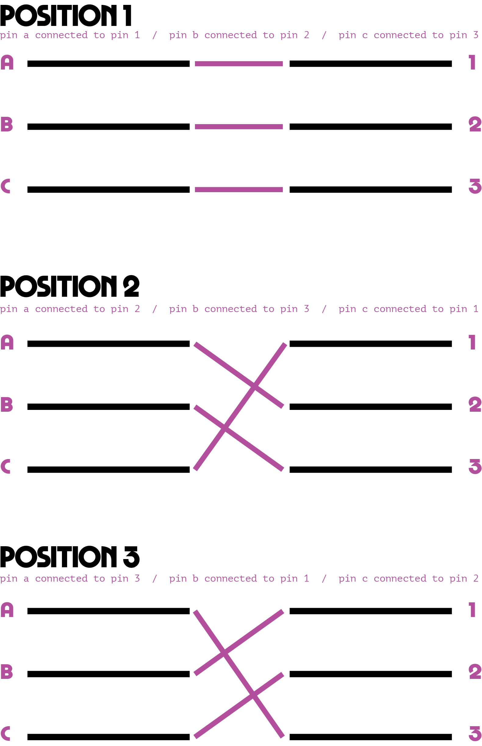
Position 1: Pin A is connected to Pin 1, Pin B is connected to Pin 2, Pin C is connected to Pin 3 Position 2: Pin A is connected to Pin 2, Pin B is connected to Pin 3, Pin C is connected to Pin 1 Position 2: Pin A is connected to Pin 3, Pin B is connected to Pin 1, Pin C is connected to Pin 2

What is the simplest way of accomplishing this circuit using a pushbutton as the control interface?

Attached is a diagram in case that helps. Pin Diagram
Thanks so much for any feedback!

\$\endgroup\$
5
  • 2
    \$\begingroup\$ You wouldn't settle for a three-way rotary switch would you? What exactly are you switching? What voltages and what current? \$\endgroup\$
    – Transistor
    Commented Nov 6, 2020 at 20:32
  • \$\begingroup\$ What are the voltage levels from A, B, C? Are they digital or analog? TTL? \$\endgroup\$
    – Reinderien
    Commented Nov 6, 2020 at 20:32
  • \$\begingroup\$ The pins are all analog signals below 5V, below 20mA. The pushbutton is to store a series of patches for a synth. Rotary switch might be the way to go because it would be so simple! But I am trying to create an all pushbutton interface. \$\endgroup\$ Commented Nov 6, 2020 at 21:06
  • 1
    \$\begingroup\$ Three position pushbutton switches are extremely rare and very likely custom and almost certainly prohibitively expensive. I would take a look at an analog multiplexer. Don't bother looking for a 3:1 since they're fairly specialized; 4:1 is much more common. As for driving it with the pushbutton, you could use a small microcontroller or maybe a binary up-down counter clocked from the switch. \$\endgroup\$
    – vir
    Commented Nov 6, 2020 at 21:39
  • 2
    \$\begingroup\$ Welcome to EE.SE, Matthew. Please edit the additional information into your question rather than bury it in the comments. \$\endgroup\$
    – Transistor
    Commented Nov 6, 2020 at 22:17

4 Answers 4

4
\$\begingroup\$

Functionally, you need three 3PST switches and a stepper. Electrically, the stepper can be a CD4013 wired as a switch debouncer plus 2-bit counter. With 1x4 analog muxes, this gives four states in continuous rotation: all off, position 1, position 2, position 3, repeat.

1 - CD4013 dual D flipflop

2 - CD4052 analog muxes (three switches plus an unused spare)

1 - SPST switch

1 - resistor, debouncing

1 - capacitor, debouncing

3 - capacitors, decoupling

\$\endgroup\$
2
  • \$\begingroup\$ Thank you! That makes sense. It may or may not be worth it, but it gives me something to work with. \$\endgroup\$ Commented Nov 7, 2020 at 15:33
  • 1
    \$\begingroup\$ You are switching a relatively high signal current. Pay attention to the ON resistance of whatever switch you use. The dual 1x4 bidirectional analog switch is a common structure, so hunt around such as in the DGxxxpart number series. Also, LT makes "clickless" parts specifically for audio. \$\endgroup\$
    – AnalogKid
    Commented Nov 7, 2020 at 17:24
2
\$\begingroup\$

You're probably looking for an analog demultiplexer. Based on digital select inputs, it connects a wire with an analog signal to one of many output channels. The output channels are in high-Z when not selected.

For your situation, with 3 signals to multiplex, you may need 3 of these demultiplexers. The select lines come from your Position 1,2,3 signals. Each demultiplexer is responsible for switching one signal (A,B,C) between of one three of its outputs. Those demultiplexer outputs are connected together as your 1,2,3 outputs. When a demultiplexer's output is not selected, that's OK because it'll be high-Z.

\$\endgroup\$
2
\$\begingroup\$

There are ICs with a single-channel, single-pole, triple-throw analog switch out there, like the NX3L4357 and the TS5A3359.

Three of those could do it, but you would also have to have a two-bit counter "clocked" by the push button for the select inputs.

Problem is, of course, that these switches and the counter don't "store" a state; power off and the state is gone. The state of the select inputs would somehow have to be saved or mechanically switched.

Multi-channel stepping switches as used in old telephone exchanges come to mind, great fun, but probably not very practical for what you want.

\$\endgroup\$
2
\$\begingroup\$

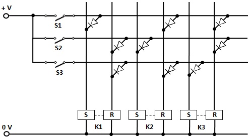
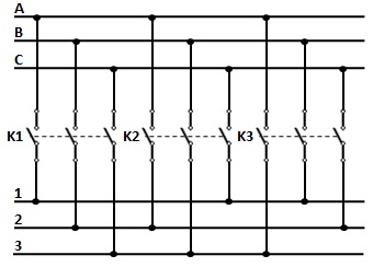
Here's a way, using 3 magnetic latch relays K1, K2, K3 and 3 push button switches S1, S2, S3.

Actuating a push button would set a corresponding relay and reset the other two.

Gold-plated contacts are a must for the relays switching low-level analog signals.

enter image description here

enter image description here

Freewheeling diodes, across the relay coils, and LED indicators are not shown.

\$\endgroup\$

Your Answer

By clicking “Post Your Answer”, you agree to our terms of service and acknowledge you have read our privacy policy.

Not the answer you're looking for? Browse other questions tagged or ask your own question.