1
\$\begingroup\$

I am completely new to the universe of hardware and I am trying to control 2 motors via my RPi 4.

The 1st step is to find out which electrode is positive and which one is negative so that when connecting to a stepper motor controller, I won't burn/damage it.

I have a toy car which I bought from Kmart. Here is its manual.

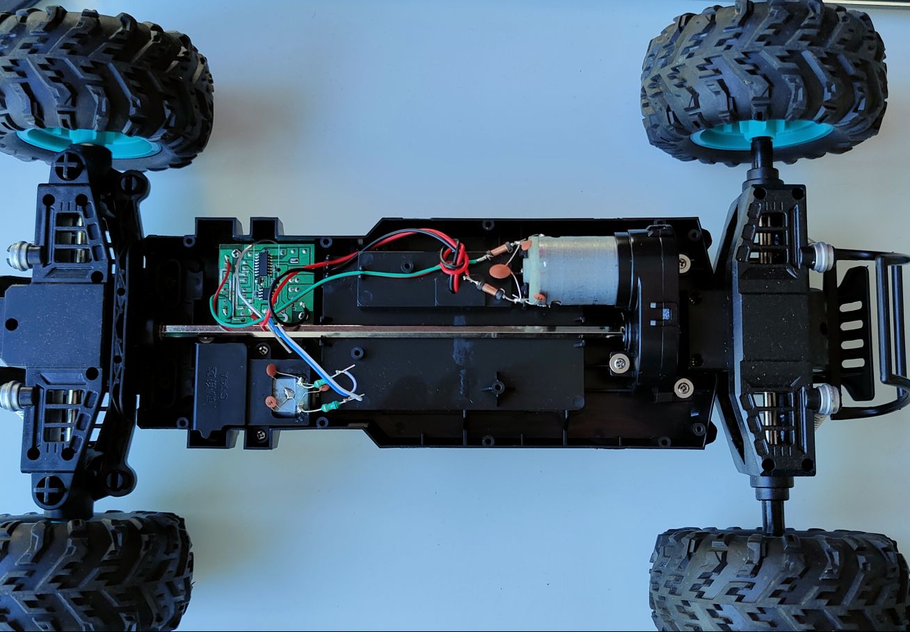
I have opened its shell and tried to figure out how to connect my RPi 4 to the two motors on this car.

After research, my understanding is I need to connect the RPi 4 to a stepper motor controller first and then connect to the motors.

Here are the photos:

car

cables

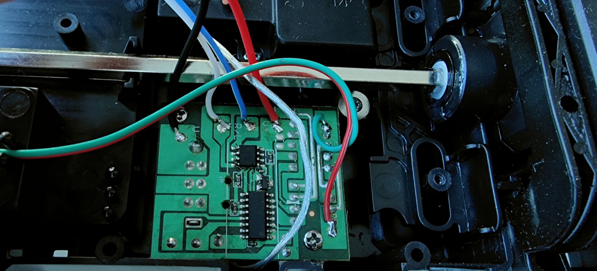
circuit

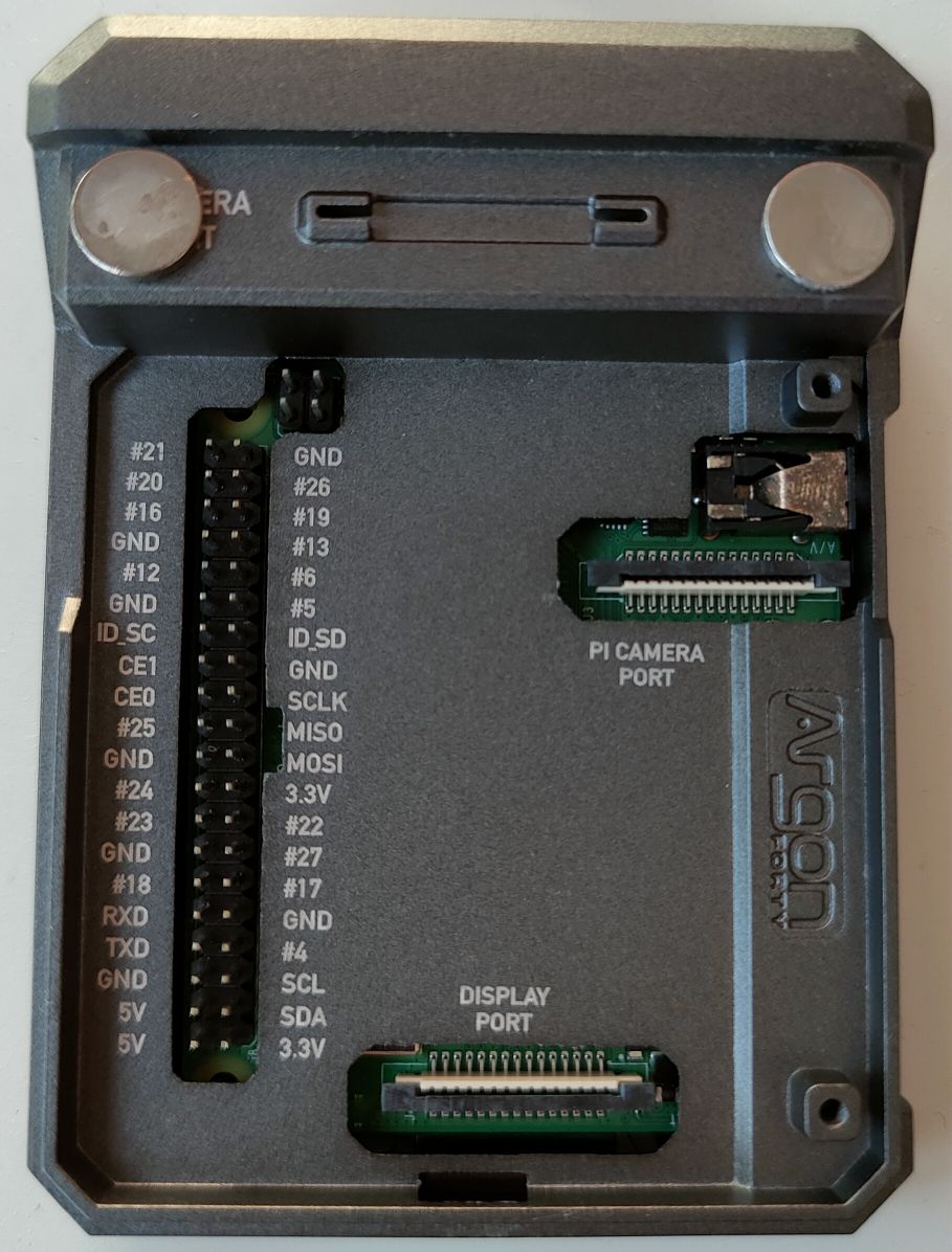
Rpi4

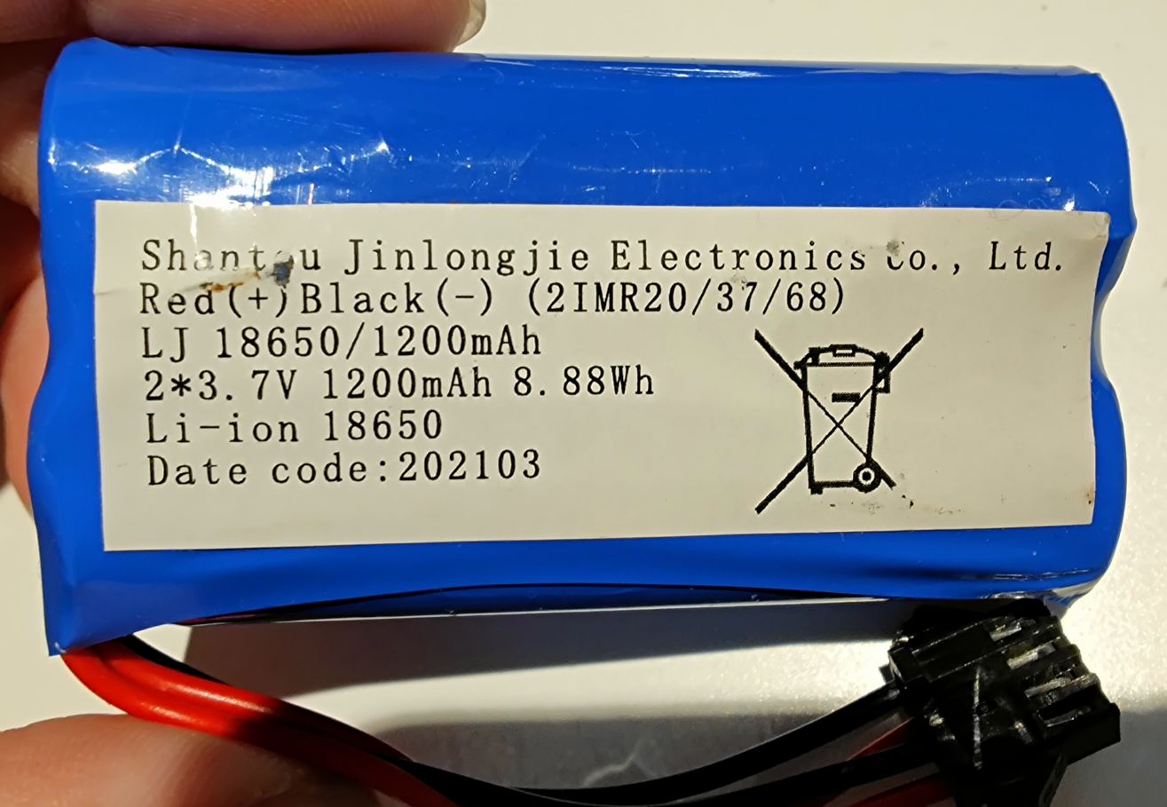
battery

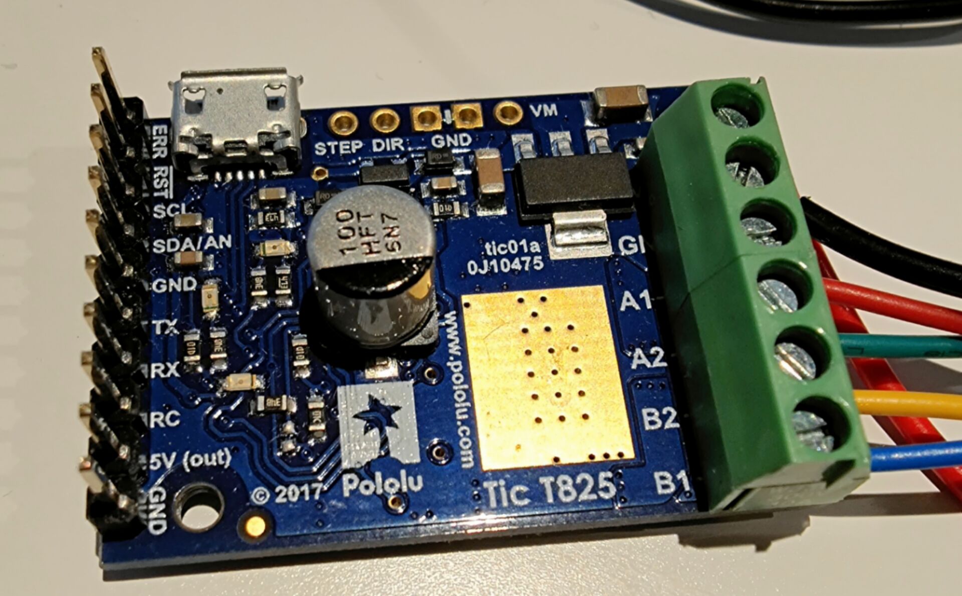
controller

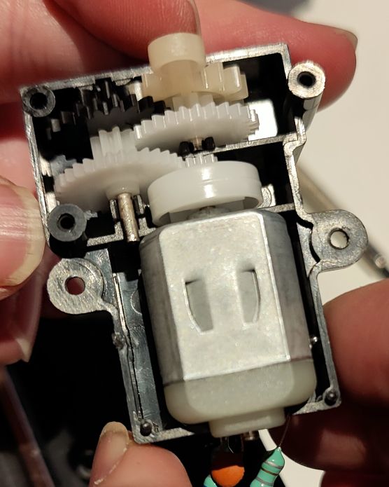
motor

turn

As you can see here, there are two motors. One is to control drive or stop, another is to control the turning.

There is no manual to the two motors.

So here are my questions:

  1. How can I tell which electrode is positive and which is negative on both motors?
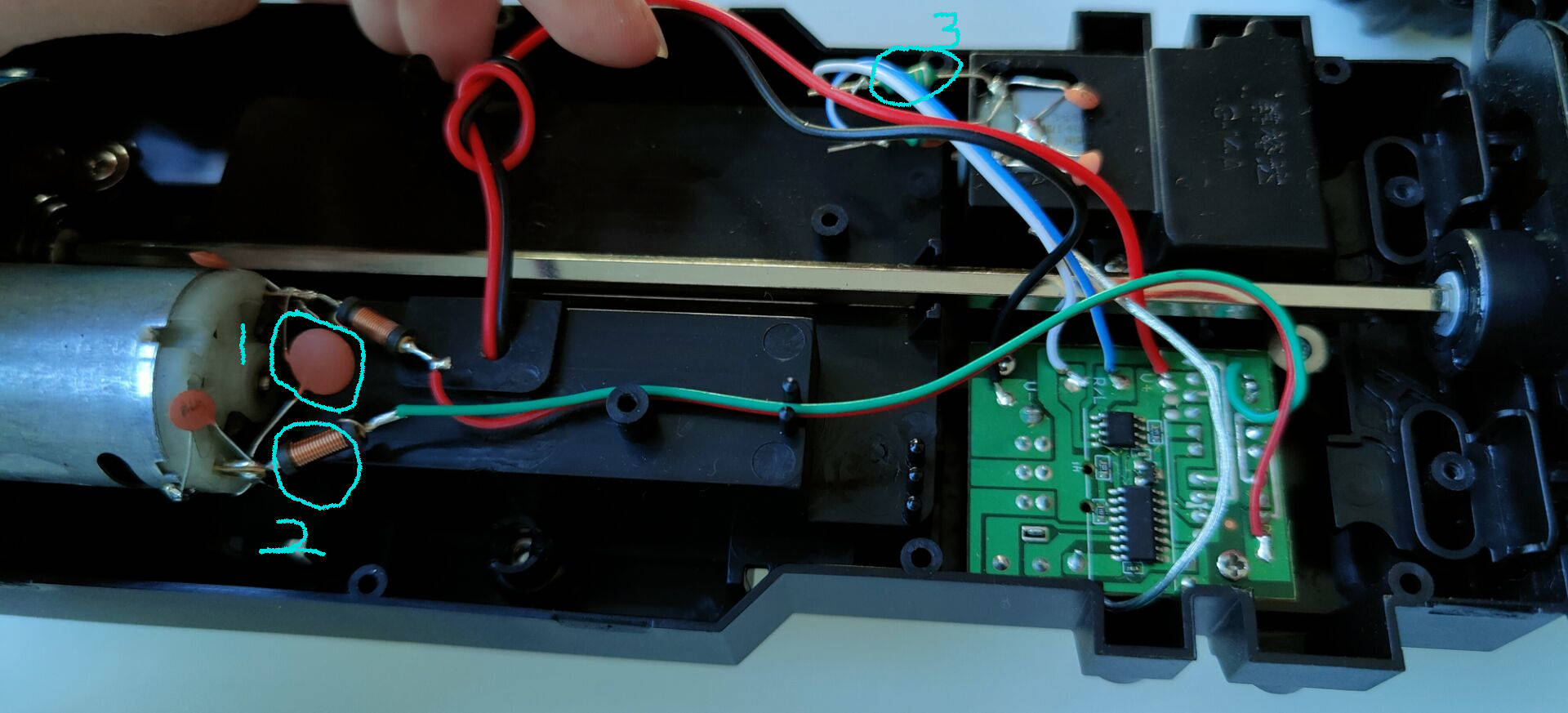
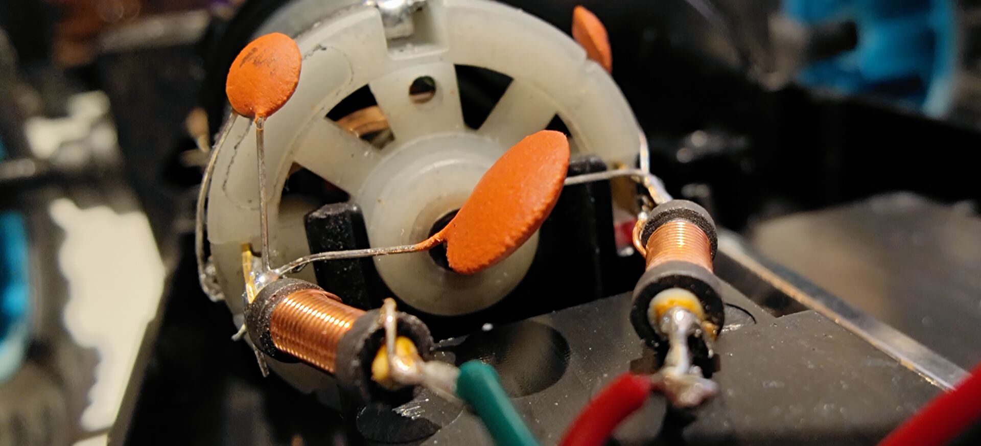
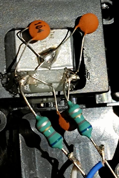
  2. What are the three things I marked in picture 2?

Update:

For the component 3 marked in the 2nd image, here is a closer look

enter image description here

Again, I'd like to control the small toy car via RPi 4.


Update 2:

Hi guys,

Thank you for your help and yes, many of you have pointed out that using Stepper Motor Controller to control DC motors are wrong and I have got your point, understood, all clear.

But check out this article, the author uses a Stepper Motor Controller to control 2 DC motors. This is why I am thinking that if he could do it with the stepper motor controller, then why I cannot do the same thing?

Could anyone explain it?

\$\endgroup\$
7
  • 6
    \$\begingroup\$ There’s no issue wiring them backwards. one way will be what you want, the other not. Suck it and see. \$\endgroup\$
    – Kartman
    Commented Aug 29, 2021 at 12:24
  • \$\begingroup\$ It doesn't make sense to modify the car because any functionality can be done via the RC controller surely? \$\endgroup\$
    – Andy aka
    Commented Aug 29, 2021 at 15:08
  • \$\begingroup\$ your whole post seems to be based on a false premise that a motor has positive and negative connections ... a lot of people will stop reading at the title ... if your post is about something else, then please change the title \$\endgroup\$
    – jsotola
    Commented Aug 29, 2021 at 17:27
  • 1
    \$\begingroup\$ please do not crosspost ... raspberrypi.stackexchange.com/questions/130917/… \$\endgroup\$
    – jsotola
    Commented Aug 29, 2021 at 17:56
  • \$\begingroup\$ @Kartman thanks for your reply. It solves one of my questions. \$\endgroup\$
    – Franva
    Commented Aug 30, 2021 at 23:05

5 Answers 5

4
\$\begingroup\$
  1. The toy has DC motors. As the car can go both forward and reverse, and steer left and right, a DC motor has no polarity in that sense.

  2. The marked components are a ceramic disc capacitor and two inductors. They filter the high frequency noise that would otherwise be emitted from the motors to low enough levels that it is legal to sell the device.

However, DC motors are not stepper motors so they are not compatible with a stepper motor controller.

\$\endgroup\$
1
  • \$\begingroup\$ thanks @Justme, for your explanation. I voted up your answer :) and thumb up for also telling me the components I circled in my photos \$\endgroup\$
    – Franva
    Commented Aug 30, 2021 at 23:11
4
\$\begingroup\$

Both are ordinary PM (permanent magnet) DC brushed motors, not steppers. They'll turn one way with with one polarity, the other way with the other. The only time you would need to identify which lead is which is to know which way they are going to turn. There is no standard for this, you just have to apply power to the motor and see which way it turns.

A stepper motor controller is the wrong thing to use. You may be able to make one work to power them if you know what you're doing (which it sounds like you don't) and can hack it to run it in some debug mode, and you are happy for the motors to run full speed either way. It would be better to use a PMDC motor controller. It would certainly be more logical to control, and would probably let you control the speed with PWM as well.

Having looked at the link you gave for the stepper controller you wanted to use, these links from the same supplier for PMDC drivers (simple) and PMDC controllers (more fully featured) would be worth looking at.

\$\endgroup\$
7
  • 1
    \$\begingroup\$ Hi @Neil_UL, the stepper motor controller I used is Polulu Tic T825(pololu.com/product/3131/specs) I don't know what's the voltage it outputs. But the car battery as you can see from the image is 7.4V, so will the stepper motor controller provide enough voltage to the 2 motors? \$\endgroup\$
    – Franva
    Commented Aug 29, 2021 at 12:58
  • 1
    \$\begingroup\$ @Franva, Niel and others have explained that you have the wrong controller for those motors. "I want to make carrot soup. I've bought cucumbers." Can you see the problem? \$\endgroup\$
    – Transistor
    Commented Aug 29, 2021 at 14:10
  • 1
    \$\begingroup\$ @Franva The T825 has a minimum input voltage of 8.5 V. It's also a stepper motor controller, which is the wrong thing to use for a PMDC motor. Rather like trying to write a novel with a badminton raquet - you could probably make it work by tying a pencil on the end, but it's not the right thing to use. \$\endgroup\$
    – Neil_UK
    Commented Aug 29, 2021 at 14:43
  • 2
    \$\begingroup\$ @Franva I've added links for suitable drivers to my answer. \$\endgroup\$
    – Neil_UK
    Commented Aug 29, 2021 at 14:58
  • \$\begingroup\$ Thanks @Neil_UK, I will check out the link you provided. I have added a section :update 2. In which section, there is a link to a article which teaches how to use Stepper Motor Controller(SMC) to control DC motors. Could you please explain why he can do it with SMC and why I cannot do the same?? \$\endgroup\$
    – Franva
    Commented Aug 30, 2021 at 11:39
3
\$\begingroup\$
  1. They're normal DC motors (not stepper). So there's no question of stepper motor controllers.

  2. The red may be positive and green negative. You may check that with a multimeter when the motors are energized.

  3. Component marked 1 is a ceramic capacitor, 2 is an EMI choke and 3 is not clear.

  4. It's a fully wired radio controlled car. What's the purpose of Raspberry Pi?

\$\endgroup\$
5
  • 1
    \$\begingroup\$ hi there, thanks for your reply. I have uploaded a new photo for the component 3, please have a look. Also the purpose of RPi is that I will run an AI model on the RPi 4 and via the RPi to control the car moving forward/backward, turn left/right. \$\endgroup\$
    – Franva
    Commented Aug 29, 2021 at 12:49
  • 2
    \$\begingroup\$ Franva, They could also be inductors (EMI chokes). I notice that the leads to this motor are grey and blue. Motor leads need not be disturbed. Related relays/transistors switched by the radio controls are to be now controlled by Raspberry Pi outputs. \$\endgroup\$
    – vu2nan
    Commented Aug 29, 2021 at 14:32
  • 1
    \$\begingroup\$ thanks @vu2nan, I now added Update 2. Could you please have a look? \$\endgroup\$
    – Franva
    Commented Aug 30, 2021 at 11:40
  • \$\begingroup\$ Franva, Yes, that article does describe how the same hardware, with the necessary software, could be used to switch four solenoids or run two DC motors forward and reverse at variable speed or one stepper motor likewise with positioning included. \$\endgroup\$
    – vu2nan
    Commented Aug 30, 2021 at 19:24
  • \$\begingroup\$ Thanks @vu2nan, thanks for telling me the parts I circled in my picture. I found out why the guy in the article I provided can use that controller to control DC motors whereas mine doesn't work. Coz that controller is a general controller which can control both DC and stepper motors. I up voted your answer. \$\endgroup\$
    – Franva
    Commented Aug 30, 2021 at 23:14
3
\$\begingroup\$

As pointed out several times already, a stepper motor controller is the wrong component to use to control these DC brushed motors. They are not steppers.

Instead you should consider using relays to switch on and off the original remote control controls. Drive to relays from your Raspberry Pi and use the relay contacts to switch the original control circuits on the remote.

Be aware that there's no feedback on the steering and that that it will probably not run in a straight line for you and repeatable performance will not be possible without position feedback or or location sensing.


But check out this article, the author uses a Stepper Motor Controller to control 2 DC motors. This is why I am thinking that if he could do it with the stepper motor controller, then why I cannot do the same thing?

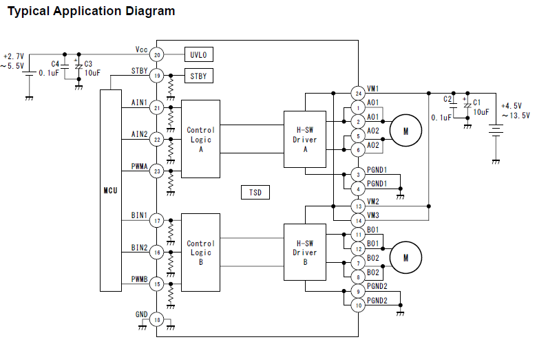
The HowChoo article you linked to is not using a stepper module - it's using a dual DC motor driver based on the Toshiba TB6612FNG. This is much more suitable for your project.

enter image description here

*Figure 1. The TB6612FNG is designed to drive two brushed DC motors via H-bridges which will allow forward and reverse operation while PWM will enable speed control.

\$\endgroup\$
3
  • \$\begingroup\$ Hi @transistor, thanks for your help. Yes many people have pointed out that stepper controller is not for the DC motors and I have got the point, all clear. What I don't understand is why this article(howchoo.com/g/mjg5ytzmnjh/…) could use a Stepper Motor Controller to control 2 DC motors? This is why I keep asking the question. Appreciated if you could explain it. \$\endgroup\$
    – Franva
    Commented Aug 30, 2021 at 11:34
  • \$\begingroup\$ Actually, according to this Toshiba datasheet you can use the board to control one stepper (4 coils) or two DC motors (1 coil each). Have a read. I'll try to answer your question in about eight hours time. \$\endgroup\$
    – Transistor
    Commented Aug 30, 2021 at 13:23
  • \$\begingroup\$ thanks @Transistor, looking forward to your update. \$\endgroup\$
    – Franva
    Commented Aug 30, 2021 at 23:15
1
\$\begingroup\$

The article is has a false assumption that the Motor driver is customized for stepper motors.

It is not. it is just a half-bridge FET driver.

  • Stepper Motors generally have:

    • 200 magnetic steps per rev and
    • quadrature phase coils (2) either unipolar with a centre-tap or bi-polar with a full bridge.
  • DC motors with brushes like these do not and have only 2 wires commutated by the designer's PWM, which is what you probably already have !

conclusion: false assumptions, no solution

\$\endgroup\$

Your Answer

By clicking “Post Your Answer”, you agree to our terms of service and acknowledge you have read our privacy policy.

Not the answer you're looking for? Browse other questions tagged or ask your own question.