0
\$\begingroup\$

I'm trying to measure inductive (not RF) reception in a short-range PKE coil antenna, and that requires a tuned circuit and outputs very low voltage.

Does it make sense to measure my oscilloscope probe 1X capacitance, and then use that result in combination with another capacitor to complete the LC resonant circuit (which requires a 20pf component to work)?

Will/Does an oscilloscope probe behave properly like a real capacitor in my curcuit?

\$\endgroup\$
3
  • \$\begingroup\$ I'm not quite sure why scopes provide an x1 probe. Compared to an x10 probe, the x1 probe has more capacitance and thus much lower bandwidth. All scope inputs are incredibly sensitive, showing microvolts, so I struggle to see where any x1 probe is ever needed. Sometimes I use an x100 probe just to get more bandwidth. \$\endgroup\$
    – rdtsc
    Commented Oct 22, 2021 at 12:21
  • 2
    \$\begingroup\$ @rdtsc Microvolts? Noise floor might be 10,000uVp-p with a x10 probe and 1000uV with x1. Of course if you only do digital, that's fine. \$\endgroup\$ Commented Oct 22, 2021 at 12:37
  • \$\begingroup\$ My rough understanding is that the X1 and X10 switch changes the sensitivity (and capacitance as a result) of the probe, right? Since I did not spend $30,000 on my scope, all 3 'scopes I've got are the same sensitivity as most hobby scopes on the market, and my signal vanishes into a straight line at about 50cm distance from the signal source, even though I know there's still a signal available somehow at 2 meters distance. \$\endgroup\$ Commented Oct 23, 2021 at 22:46

2 Answers 2

2
\$\begingroup\$

Yes, oscilloscope inputs do present a capacitive load to the circuit under test. There is capacitance both in the probe itself and the scope input. In many cases that can be ignored as it is very small compared to the circuit's capacitance.

But for some applications it cannot be ignored and does change the behavior of the circuit. The chances are that your multimeter capacitance input is not going to give you an accurate reading. Usually the best way to get a reasonable value for test equipment components is to read the manufacturer's specification sheet. For every scope or probe I've used, this information is provided.

\$\endgroup\$
1
  • \$\begingroup\$ I think it cannot be ignored in my specific case. Commercial components for this coil have selectable resonance capacitors which vary upto 32pf in 1pf increments, and my test meter shows about 27pf on my probes (and an interesting signal on the scope while testing the probe too)... leading me to believe that I probably can't use a plain oscilloscope to look at this circuit at all ? \$\endgroup\$ Commented Oct 23, 2021 at 22:51
1
\$\begingroup\$

Most general-purpose oscilloscopes have an input that is both resistive and capacitive - the capacitance varies from 'scope -to- 'scope but is pretty much constant for any particular model:

  • Resistor: 1,000,000 ohms
  • Capacitor: 15-30 pico farads.

These two components appear in parallel, and should not vary much on different Y-channel sensitivity ranges.

Many mutltimeters measure capacitance crudely and may have trouble with these small capacitances. The \$1M\Omega\$ input resistor might also cause problems, either causing a reading failure, or degrading accuracy of the capacitance measurement.
The \$1M\Omega\$'s effect can be made insignificant by using a high-frequency test signal above 1 MHz. You generally have no choice with a multimeter capacitance measurement.

Even if you can measure the oscilloscope's input capacitance, stray capacitance of the connecting wires to your coil-under-test can cause some error, especially if they are long. A coaxial cable between coil-and-scope should not be used - its capacitance would dominate any you add. A BNC-to-banana adapter will add some capacitance as well.
If you are resonating a coil with capacitance, you can expect that any device meant to sense a signal will have some capacitance, which will differ from your oscilloscope measurement, and will shift resonance to a different frequency. In such a case, a variable resonating capacitor is used so that resonance can be tuned to a desired frequency in the final circuit.
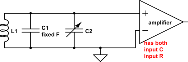
schematic

simulate this circuit – Schematic created using CircuitLab

\$\endgroup\$

Your Answer

By clicking “Post Your Answer”, you agree to our terms of service and acknowledge you have read our privacy policy.

Not the answer you're looking for? Browse other questions tagged or ask your own question.