0
\$\begingroup\$

I asked and learned that a BMS doesn't control charge current.
BMS adjusting charge current
I need to reduce charge current beacuse the wall adapter can provide a maximum of 1 A, the batteries draw a lot of current while they're are charging.
From the internet the solution can be

  1. Adding current limiting circuit.
  2. Adding a charger circuit.

Considering the load always stays connected even during the charging process. This is a requirement.
I don't have much experince in this area. I would be very grateful if you could suggest IC and circuit topology.
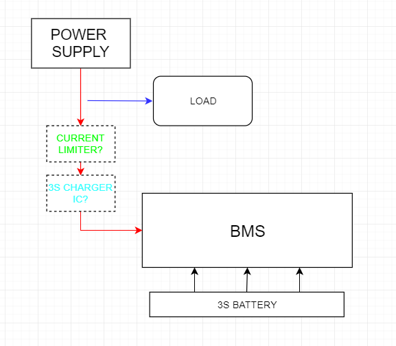
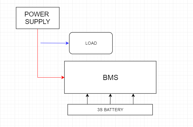
This is my old opinion:
enter image description here

Probably, this is the what I need:

enter image description here
Please suggest correct components and circuit structure.

\$\endgroup\$
6
  • \$\begingroup\$ What voltage does your power supply output? If higher than 3x4.2 V, then a battery charger IC based on a buck converter with constant current limiting would be my suggestion. \$\endgroup\$
    – winny
    Commented Dec 20, 2021 at 12:57
  • \$\begingroup\$ Actually it's a standart 12V wall adapter. But if it's mandotary i can replace it with 12.6V one. \$\endgroup\$
    – berker
    Commented Dec 20, 2021 at 13:03
  • \$\begingroup\$ Also, if you have specific suggestion link/schematic/part number that would be great. \$\endgroup\$
    – berker
    Commented Dec 20, 2021 at 13:04
  • \$\begingroup\$ At 12.0 V, you’ll need buck-boost or the batteries will never be fully charged. Easiest solution is to get a 15 or 24 V supply and just regular buck. Product recommendations are off-topic here, but a search for “li-ion buck charger IC” should get you started. \$\endgroup\$
    – winny
    Commented Dec 20, 2021 at 13:16
  • \$\begingroup\$ It doesn't need fully charged. Batteries just for backup purposes. Well, what do you think about 3S 18650 configuration? I need about 200-300mA continuous current. Do you suggest an alternative battery type? \$\endgroup\$
    – berker
    Commented Dec 20, 2021 at 13:29

1 Answer 1

1
\$\begingroup\$

Separate current limiting is not a correct approach. If you have 1A current limiting and then a 2A charger then the charger tries to take 2A and can't so it might shut down.

The only working approach is to have a charger that charges at 1A.

\$\endgroup\$
6
  • \$\begingroup\$ Nice. You suggest charger circuit. I hope, i have options for 3S batteries. \$\endgroup\$
    – berker
    Commented Dec 20, 2021 at 13:54
  • \$\begingroup\$ I disagree. What if the user wants to use and charge at the same time? Good UX. Crappy products can't be used and charged at the same time. \$\endgroup\$
    – winny
    Commented Dec 20, 2021 at 14:31
  • \$\begingroup\$ @winny then set the charger to chargle with less current so the device can be used while charging. Point was not to take the charge current literally. If the load is connected to battery, then the whole 1A can be fed to batteries while the load draws current. \$\endgroup\$
    – Justme
    Commented Dec 20, 2021 at 14:41
  • \$\begingroup\$ I see now where the confusion comes from. What if op have a power supply which just gives out CV and have a downstream buck or similar to charge the battery? Then he can use and charge at the same time. \$\endgroup\$
    – winny
    Commented Dec 20, 2021 at 14:44
  • \$\begingroup\$ @winny In case of power supply doesn't exist, batteries can be supply current to load? If i use charger circuit, because doesn't charger behave like a one way bridge? \$\endgroup\$
    – berker
    Commented Dec 21, 2021 at 10:13

Your Answer

By clicking “Post Your Answer”, you agree to our terms of service and acknowledge you have read our privacy policy.

Not the answer you're looking for? Browse other questions tagged or ask your own question.