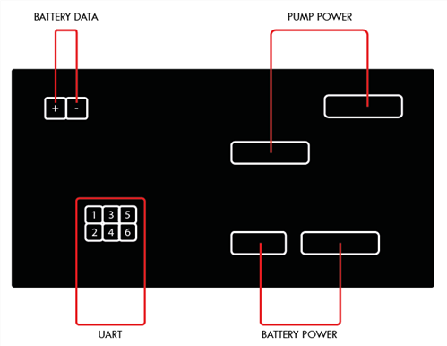
I have a garden and would like to water it automatically with rain. For this I bought a «Gardena Battery Rain Water Tank Pump 2000/2» and would like to control via an ESP8266.
After opening the control panel, I found that the board is molded in black plastic, but there is an interface with 6 ports.
I checked this interface with a logic analyzer and identified the following ports:
- 1 > TX,
- 2 > GND
- 3 > RX
As soon as the device is switched on, RX and TX switch to high and data is sent via TX. When switched off, they remain high and go low after 10 seconds.
The baudrate is 9600 8N1 and I think the interface type is UART.
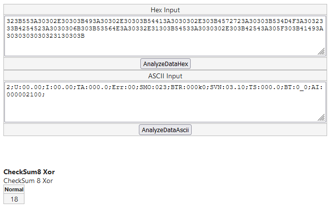
I receive the following data formatted as HEX:
FE323B553A30302E30303B493A30302E30303B54413A3030302E303B4572723A30303B534D4F3A3032333B4254523A3030306B303B53564E3A30332E31303B54533A3030302E303B42543A305F303B41493A3030303030323130303B18FD
FE323B553A32302E34313B493A30302E30303B54413A3032352E343B4572723A30303B534D4F3A3032333B4254523A3034376B353B53564E3A30332E31303B54533A3032352E373B42543A335F313B41493A3030303030323130313B19FD
FE323B553A32302E34303B493A30302E30303B54413A3032352E343B4572723A30303B534D4F3A3032333B4254523A3034376B353B53564E3A30332E31303B54533A3032352E383B42543A335F313B41493A3030303034313130323B13FD
FE323B553A32302E34303B493A30302E30303B54413A3032352E343B4572723A30303B534D4F3A3032333B4254523A3034376B353B53564E3A30332E31303B54533A3032352E383B42543A335F313B41493A3030303034313130333B12FD
HEX converted to ASCII:
þ2;U:00.00;I:00.00;TA:000.0;Err:00;SMO:023;BTR:000k0;SVN:03.10;TS:000.0;BT:0_0;AI:000002100;ýþ2;U:20.41;I:00.00;TA:025.4;Err:00;SMO:023;BTR:047k5;SVN:03.10;TS:025.7;BT:3_1;AI:000002101;ýþ2;U:20.40;I:00.00;TA:025.4;Err:00;SMO:023;BTR:047k5;SVN:03.10;TS:025.8;BT:3_1;AI:000041102;ýþ2;U:20.40;I:00.00;TA:025.4;Err:00;SMO:023;BTR:047k5;SVN:03.10;TS:025.8;BT:3_1;AI:000041103;ý
I think 0xFE is the start and 0xFD is the end byte.
To create the checksum, start reading after the first byte, end before the checksum byte and calculate the checksum using the CheckSum8 Xor algorithm.
As soon as I send data, I get "0xFF" as output followed by a start and end byte with the data listed above. I assume that 0xFF is an error code.
I have looked at the sent data with the logic analyzer and the scheme of the sent corresponds to the received.
Do you have any idea what kind of protocol this is?
Update: 2022/04/28
I tried to send various data to the RX interface, here is my result:
0x00 > return 0xFF followed by the data
0x01 > return 0xFF followed by the data
0x02 > return 0xFF followed by the data

0xE0 > return the data without 0xFF
0xE1 > return the data without 0xFF
0xE2 > no return, but if the value was sent twice, data will be sent
0xE3 to 0xFF > no return

0xFE, 0x32, 0xFD > no return
0xFE, 0x32, 0x3B, 0xFD > no return
0xFE, 0x32, 0x3B, 0x49, 0xFD > no return
0xFE, 0x32, 0x3B, 0x00, 0xFD > return 0xFF followed by the data
0xFE, 0x32, 0x3B, 0x00, 0x3A, 0xFD > return the data without 0xFF
0xFE, 0x32, 0x3B, 0x00, 0x3A, 0x30, 0xFD > return 0xFF followed by the data
Update: 2022/07/06
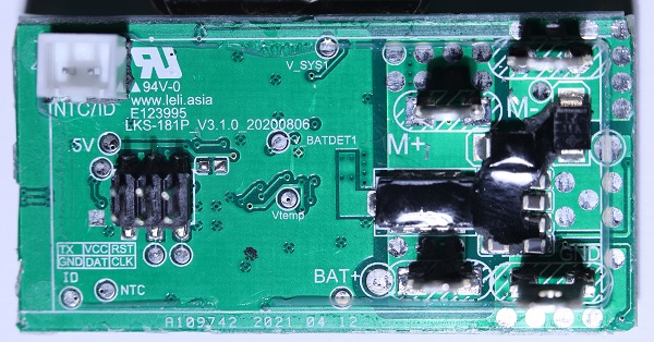
I was now able to detach the plastic from the board. On the board it has an imprint with the pinout.
- TX
- GND
- VCC
- DAT
- RST
- CLK
The interface reminds me of ICSP, but the labeling is not identical. Unfortunately, I don't see any RX. Could DAT possibly be RX?
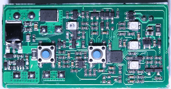
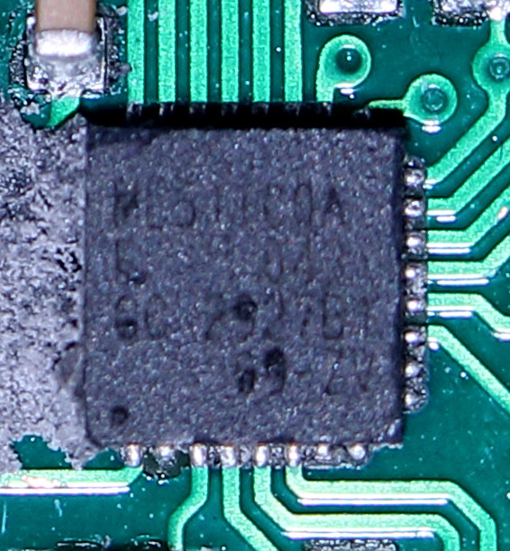
I can't completely decipher the labeling of the microcontroller. The following I could read:
- 511CD?
- 043
- (CC or DD) 2?27(8 or 9)1 > Example "CC 2?2781"
- ??-ZV
Update: 2022/07/08
I spent the last two days trying to identify the microcontroller.
I found NU-Link, a SWD debugger that uses the DAT, CLK and GND pins. When I searched the website of the manufacturer, I found the Nuvoton NuMicro ML51TC0AE.
Datasheet: https://www.nuvoton.com/export/resource-files/DS_ML51_ML54_ML56_Series_EN_Rev2.02.pdf
I have ordered a NU-Link from Taiwan and will try to communicate with it via SWD.
Update: 2022/08/03
I have created a new post: Gardena battery rain water tank pump 2000/2 – SWD Interface

