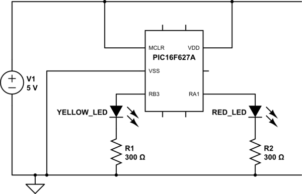
I am getting results I don't understand in a small application (I am still a learner) using PIC16F627A MCU. Schematic of the circuit:

simulate this circuit – Schematic created using CircuitLab
The C source code I have is as follows:
// CONFIG
#pragma config FOSC = INTOSCIO  // Oscillator Selection bits (INTOSC oscillator: I/O function on RA6/OSC2/CLKOUT pin, I/O function on RA7/OSC1/CLKIN)
#pragma config WDTE = OFF       // Watchdog Timer Enable bit (WDT disabled)
#pragma config PWRTE = OFF      // Power-up Timer Enable bit (PWRT enabled)
#pragma config MCLRE = ON       // RA5/MCLR/VPP Pin Function Select bit (RA5/MCLR/VPP pin function is MCLR)
#pragma config BOREN = OFF      // Brown-out Detect Enable bit (BOD disabled)
#pragma config LVP = OFF        // Low-Voltage Programming Enable bit (RB4/PGM pin has digital I/O function, HV on MCLR must be used for programming)
#pragma config CPD = OFF        // Data EE Memory Code Protection bit (Data memory code protection off)
#pragma config CP = OFF         // Flash Program Memory Code Protection bit (Code protection off)

#include <xc.h>

#define GPIO_OUTPUT 0
#define GPIO_INPUT 1

#define _XTAL_FREQ 4000000

#define RED_LED PORTAbits.RA1
#define YELLOW_LED PORTBbits.RB3

#define TIMER_RESET_VALUE 206;


long time_count;
long time_threshold = 10;  // 10 x 0.1ms = 1ms = 1kHz
long time_count_max_value = 20000;  // some sort of cutoff

void reset_timer() {
    TMR0 = TIMER_RESET_VALUE;
}

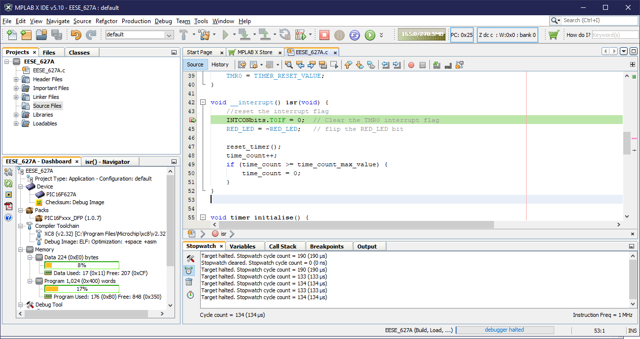
void __interrupt() isr(void) {
    //reset the interrupt flag
    INTCONbits.T0IF = 0;  // Clear the TMR0 interrupt flag
    RED_LED = ~RED_LED;   // flip the RED_LED bit

    reset_timer();
    time_count++;
    if (time_count >= time_count_max_value) {
        time_count = 0;
    }
}


void timer_initialise() {
    OPTION_REGbits.PSA = 0;     //Prescaler assigned to Timer 0

    OPTION_REGbits.PS = 0b000;  //Set the prescaler to 1:2
    OPTION_REGbits.T0CS = 0;    //Use the instruction clock (Fcy/4) as the timer
                                //clock.

    INTCONbits.T0IF = 0;        //Clear the Timer 0 interrupt flag
    reset_timer();              //Load initial value into the timer
    INTCONbits.T0IE = 1;        //Enable the Timer 0 interrupt
    INTCONbits.GIE = 1;         //Set the Global Interrupt Enable
}


void main(void) {

    // TRISA = 0xFF; // default all GPIO as inputs
    // TRISB = 0xFF; // default all GPIO as inputs

    TRISA1 = GPIO_OUTPUT; // red LED is output
    TRISB3 = GPIO_OUTPUT; // yellow LED is output
    YELLOW_LED = 0; // start with LED off
    RED_LED = 1; // start with RED_LED on

    timer_initialise();

    while (1) {
        if (time_count == time_threshold/2) {
            time_count = 0;
            YELLOW_LED = ~YELLOW_LED;
        }
    }

    return;
}
I am using MPLAB X IDE 5.40 with XC8 v2.41 compiler.
The results I get are:
- The yellow LED blinks at a frequency of 850 Hz instead of the 1 kHz I was trying to achieve
- The red LED remains on constantly instead of blinking at the 10kHz I was trying to achieve
Both were measured with oscilloscope and DMM.
I realise the objective is pretty benign but it's just an exercise I am going through to learn and practice basic concepts.

