1
\$\begingroup\$

I am getting results I don't understand in a small application (I am still a learner) using PIC16F627A MCU. Schematic of the circuit:
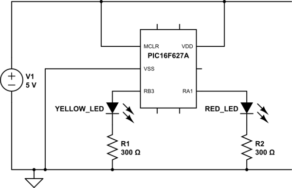
schematic

simulate this circuit – Schematic created using CircuitLab

The C source code I have is as follows:

// CONFIG
#pragma config FOSC = INTOSCIO  // Oscillator Selection bits (INTOSC oscillator: I/O function on RA6/OSC2/CLKOUT pin, I/O function on RA7/OSC1/CLKIN)
#pragma config WDTE = OFF       // Watchdog Timer Enable bit (WDT disabled)
#pragma config PWRTE = OFF      // Power-up Timer Enable bit (PWRT enabled)
#pragma config MCLRE = ON       // RA5/MCLR/VPP Pin Function Select bit (RA5/MCLR/VPP pin function is MCLR)
#pragma config BOREN = OFF      // Brown-out Detect Enable bit (BOD disabled)
#pragma config LVP = OFF        // Low-Voltage Programming Enable bit (RB4/PGM pin has digital I/O function, HV on MCLR must be used for programming)
#pragma config CPD = OFF        // Data EE Memory Code Protection bit (Data memory code protection off)
#pragma config CP = OFF         // Flash Program Memory Code Protection bit (Code protection off)

#include <xc.h>

#define GPIO_OUTPUT 0
#define GPIO_INPUT 1

#define _XTAL_FREQ 4000000

#define RED_LED PORTAbits.RA1
#define YELLOW_LED PORTBbits.RB3

#define TIMER_RESET_VALUE 206; 


long time_count;
long time_threshold = 10;  // 10 x 0.1ms = 1ms = 1kHz
long time_count_max_value = 20000;  // some sort of cutoff

void reset_timer() {
    TMR0 = TIMER_RESET_VALUE;
}

void __interrupt() isr(void) {
    //reset the interrupt flag
    INTCONbits.T0IF = 0;  // Clear the TMR0 interrupt flag
    RED_LED = ~RED_LED;   // flip the RED_LED bit
    
    reset_timer();
    time_count++;
    if (time_count >= time_count_max_value) {
        time_count = 0;
    }    
}


void timer_initialise() {
    OPTION_REGbits.PSA = 0;     //Prescaler assigned to Timer 0 

    OPTION_REGbits.PS = 0b000;  //Set the prescaler to 1:2 
    OPTION_REGbits.T0CS = 0;    //Use the instruction clock (Fcy/4) as the timer
                                //clock. 

    INTCONbits.T0IF = 0;        //Clear the Timer 0 interrupt flag
    reset_timer();              //Load initial value into the timer
    INTCONbits.T0IE = 1;        //Enable the Timer 0 interrupt    
    INTCONbits.GIE = 1;         //Set the Global Interrupt Enable
}


void main(void) {

    // TRISA = 0xFF; // default all GPIO as inputs
    // TRISB = 0xFF; // default all GPIO as inputs
    
    TRISA1 = GPIO_OUTPUT; // red LED is output
    TRISB3 = GPIO_OUTPUT; // yellow LED is output
    YELLOW_LED = 0; // start with LED off
    RED_LED = 1; // start with RED_LED on
    
    timer_initialise();
    
    while (1) {
        if (time_count == time_threshold/2) {
            time_count = 0;
            YELLOW_LED = ~YELLOW_LED;
        }
    }
    
    return;
}

I am using MPLAB X IDE 5.40 with XC8 v2.41 compiler.

The results I get are:

  1. The yellow LED blinks at a frequency of 850 Hz instead of the 1 kHz I was trying to achieve
  2. The red LED remains on constantly instead of blinking at the 10kHz I was trying to achieve

Both were measured with oscilloscope and DMM.

I realise the objective is pretty benign but it's just an exercise I am going through to learn and practice basic concepts.

\$\endgroup\$
15
  • \$\begingroup\$ Could 1) be an off-by-one error? \$\endgroup\$
    – Hearth
    Commented Jun 6, 2023 at 15:21
  • \$\begingroup\$ Ah! Could be! With prescaler at 1:2 you're right, I recall there should be an adjustment of 1. Let me try... \$\endgroup\$
    – RickyBoy
    Commented Jun 6, 2023 at 15:29
  • \$\begingroup\$ I'd write that as an answer, but I don't think I can help with 2), so it'd be an incomplete answer. \$\endgroup\$
    – Hearth
    Commented Jun 6, 2023 at 15:37
  • 1
    \$\begingroup\$ Is this a chip where the comparator is active by default? If you want RA1 to be a digital I/O, you might try disabling the comparator...CMCON=0x07. Haven't used this chip, so am unsure - this addresses the constantly-ON RED LED. \$\endgroup\$
    – glen_geek
    Commented Jun 6, 2023 at 15:55
  • 2
    \$\begingroup\$ This is an 8 bit MCU and you use variables of type long, which need 4 memory read cycles to fetch the value. But the interrupt code may modify such a value in the middle of a read access of the main loop. Such variables must be declared as "volatile" and the access in the main thread must be surrounded by disable and enable interrupt calls. \$\endgroup\$
    – Jens
    Commented Jun 6, 2023 at 17:53

2 Answers 2

4
\$\begingroup\$

When TMR0 overflows, its interrupt is triggered, while TMR0 merrily keeps incrementing every microsecond...TMR0 has already incremented some few # counts before it gets reset to its new value.

  • Since interrupts act like a CALL, TMR0 has already incremented by at least two at the beginning of interrupt routine.
  • Flipping the RED LED takes at least another microsecond, and increments TMR0 by another count.
  • Calling reset_timer() is another call - 2 more microseconds, and 2 more TMR0 counts
  • Actually writing the new value to TMR0 takes another microsecond.

There may be more microseconds lost if the interrupt routine saves W and flags. All these extra microseconds extend the time between TMR0 writes (which lowers the frequency)

In any case, you should likely change reset_timer()

void reset_timer() {
    TMR0 -= TIMER_RESET_VALUE;
}

Or change the interrupt routine:

    void __interrupt() isr(void) {
    TMR0 -= TIMER_RESET_VALUE;
    //reset the interrupt flag
    INTCONbits.T0IF = 0;  // Clear the TMR0 interrupt flag
    RED_LED = ~RED_LED;   // flip the RED_LED bit
    time_count++;
    if (time_count >= time_count_max_value) {
       time_count = 0;
       }
    }

EDIT:
Subtracting a constant from a running timer can miss or add counts, depending on when the subtract actually takes effect. I cobbled up this interrupt structure in ASM (since I don't trust micro-compilers) to see if pipeline or other timing issues affect TMR0 period.

I would have guessed that TIMER_RESET_VALUE would be near 100 to interrupt every 100 microseconds. But subtracting a value of 97 resulted in 100us interrupt period - it seems that TMR0 stalls a few counts after the subtract...at least that's what MPLAB's Simulator tells me.
A compiled ISR may operate differently, requiring a tweak to TIMER_RESET_VALUE. If more predictable delays are required, the whole LED-flashing process would be better done in PWM mode with TMR2...using PR2 to set the period. NO ISR required to flash the RED LED. It is a more-complex thing to configure.


For some reason, Microchip thinks users prefer to use the two internal comparators, which over-rides the use of PORTA GPIO least-two-significant bits.
So if you want to use RA0 or RA1 as general-purpose I/0, you must disable comparator function by setting CMCON=0x07, rather than its power-on default of 0x00.

Multi-function I/O pins are a pain to re-configure, but add versatility. MPLAB X IDE 5.4 may do the reconfiguration for you, if you use all its configuration features.

\$\endgroup\$
3
  • \$\begingroup\$ Thanks for this answer, lots of very useful info. I wonder whether: a) the reset should be TMR += TMR_RESET_VALUE b) the reset should be the last line of the ISR I did this and I now have both LEDs only 1% off-target. (Agree about the use of PWM - this exercise was simply one for me to learn the use of timers and their interrupts - the ultimate application requires it) \$\endgroup\$
    – RickyBoy
    Commented Jun 7, 2023 at 9:53
  • 1
    \$\begingroup\$ RickyBoy - "-=" or "+=" as you please. When you leave home, do you count the kilometers from home, or kilometers to your destination? Consider code readability for someone else. Slightly safer to add/subtract TMR0 early in the ISR while its count value is low, to avoid potential math overflow if TMR_RESET_VALUE approaches 255. \$\endgroup\$
    – glen_geek
    Commented Jun 7, 2023 at 12:28
  • \$\begingroup\$ Thanks very much \$\endgroup\$
    – RickyBoy
    Commented Jun 7, 2023 at 14:47
1
\$\begingroup\$

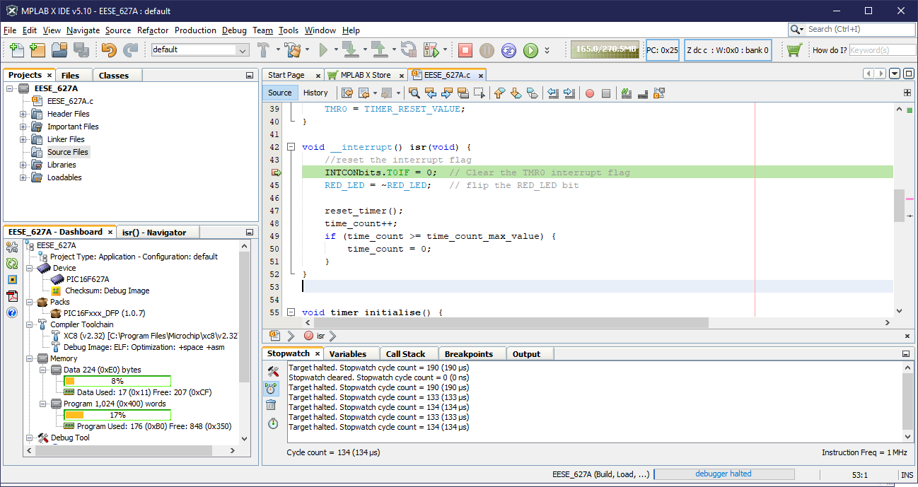
I was able to load and run the OP's original project, and the simulator stopwatch shows the timer interrupt occurring at 133 us intervals. The yellow LED toggles with about 660-675 us. The PICkit3 is in the list of available debuggers.

This is primarily to see that the project will run using the simulator.

MPLABX IDE

\$\endgroup\$
1
  • \$\begingroup\$ Thanks to you I am able to use the debugger now. I feel I should share the code I now have (with all the great tips and advice I have been given) which works perfectly as far as I know. But being new to this forum should I submit it as an answer, or an edit to the original post? \$\endgroup\$
    – RickyBoy
    Commented Jun 8, 2023 at 16:03

Your Answer

By clicking “Post Your Answer”, you agree to our terms of service and acknowledge you have read our privacy policy.

Not the answer you're looking for? Browse other questions tagged or ask your own question.