0
\$\begingroup\$

I am trying to read from a register in MAX17320 using I2C protocol but get always HAL_Error message. I have the chip MAX17320 and a microcontroller STM32F105, when I try to read from the register nDeviceName(121h) to see that the chip is working I get HAL_ERROR message.

As far as I understood, the slave address is 0x16 and the memory address for the specific register is 0x21 and the this register contains for a total of 5 words of data. I am writing this the code in STM32 Cube IDE.

It would be enormous help if someone could help me with this. This the link for the chip MAX17320: https://www.analog.com/media/en/technical-documentation/data-sheets/MAX17320.pdf

This is how I implemented the code:

HAL_StatusTypeDef MAX30205_readTemp(uint8_t dev_address)
{
    HAL_StatusTypeDef ret;
    uint8_t tempData[10];
    // Get temperature data, reg 0, two bytes
    ret = HAL_I2C_Mem_Read(&hi2c1, (uint16_t)(dev_address)|0x01, 0x21, 1, tempData, 10, 50);
    if(ret != HAL_OK)
    {
        return ret;
    }
}

Call the function
uint8_t dev_address = 0x16;
 
  while (1)
  {
      MAX30205_readTemp(dev_address);
      HAL_Delay(100);
  }

thanx to @Justme and @Jim Fischer, for your answer, but unfortunately I couldn't figure it out what the problem is. this I try to provide more details if someone know what the problem is. The problem is that I still get a HAL_ERROR instead of HAL_OK when I debug the function:

ret = HAL_I2C_Mem_Read(&hi2c1, dev_address, 0x21, 1, tempData, 10, HAL_MAX_DELAY);

This is the whole code that I have written in STM32 CUbe IDE:

HAL_StatusTypeDef MAX30205_readTemp(uint8_t dev_address)
{
    HAL_StatusTypeDef ret;
    uint64_t tempData[10];
     
    // read from the register sDeviceName 
    ret = HAL_I2C_Mem_Read(&hi2c1, dev_address, 0x21, 1, tempData, 10, HAL_MAX_DELAY);
    if(ret != HAL_OK)
    {
        return ret;
    }
    return HAL_OK;
}

Here I call the function:

uint8_t dev_address = 0x16|0x01;

  /* USER CODE BEGIN WHILE */
  while (1)
  {

    MAX30205_readTemp(dev_address);
      HAL_Delay(100);
  }
  /* USER CODE END 3 */

When I debug the code, I step into

ret = HAL_I2C_Mem_Read(&hi2c1, dev_address, 0x21, 1, tempData, 10, HAL_MAX_DELAY);

And after that, I come to these lines of code:

/* Send Slave Address and Memory Address */
 if (I2C_RequestMemoryRead(hi2c, DevAddress, MemAddress, MemAddSize, Timeout, tickstart) != HAL_OK)
    {
      return HAL_ERROR;
    }

When I step into this if statement I come to this lines of code:

 /* Send slave address */
  hi2c->Instance->DR = I2C_7BIT_ADD_WRITE(DevAddress);

  /* Wait until ADDR flag is set */
  if (I2C_WaitOnMasterAddressFlagUntilTimeout(hi2c, I2C_FLAG_ADDR, Timeout, Tickstart) != HAL_OK)
  {
    return HAL_ERROR;
  }

then I step into the if statement, I come into this lines of code:

static HAL_StatusTypeDef I2C_WaitOnMasterAddressFlagUntilTimeout(I2C_HandleTypeDef *hi2c, uint32_t Flag, uint32_t Timeout, uint32_t Tickstart)
{
  while (__HAL_I2C_GET_FLAG(hi2c, Flag) == RESET)
  {
    if (__HAL_I2C_GET_FLAG(hi2c, I2C_FLAG_AF) == SET)
    {
      /* Generate Stop */
      SET_BIT(hi2c->Instance->CR1, I2C_CR1_STOP);

      /* Clear AF Flag */
      __HAL_I2C_CLEAR_FLAG(hi2c, I2C_FLAG_AF);

      hi2c->PreviousState       = I2C_STATE_NONE;
      hi2c->State               = HAL_I2C_STATE_READY;
      hi2c->Mode                = HAL_I2C_MODE_NONE;
      hi2c->ErrorCode           |= HAL_I2C_ERROR_AF;

      /* Process Unlocked */
      __HAL_UNLOCK(hi2c);

      return HAL_ERROR;
    }

After that it just return a HAL_ERROR and goes back to where I call the function. for me it seems that the device adress 0x16|0x10 = 0x17 does not acknowledges and that is why I got an HAL_ERROR, but maybe I am wrong. According to the datasheet for MAX17320, the device address is either 0x16 or 0x6C. And for this particular register sDeviceName (0x121) the device address 0x16 should be used. If someone know the problem please let me know.

\$\endgroup\$
14
  • 1
    \$\begingroup\$ If you don't get HAL_OK, what error you get then? This defines how to proceed. \$\endgroup\$
    – Justme
    Commented Jun 17, 2023 at 14:58
  • \$\begingroup\$ Ali - Hi, I have improved the code formatting to match what you wrote in your duplicate (now deleted) question. Please read the tour & help center to see the main site rules and to see how Stack Exchange differs from typical forums e.g. on Stack Exchange, questions can be edited to improve them e.g. to clarify, add new info, make them easier to read etc. (although changes should not be made which invalidate existing answers). \$\endgroup\$
    – SamGibson
    Commented Jun 17, 2023 at 16:04
  • \$\begingroup\$ I should get HAL_OK but I get HAL_ERROR. I forgot to add HAL_OK at the end of the code \$\endgroup\$
    – Ali
    Commented Jun 17, 2023 at 16:13
  • \$\begingroup\$ #Justme I get HAL_ERROR instead of HAL_OK. I do not know why I get HAL_ERROR and do not know what I missed. If you see the problem please let me know \$\endgroup\$
    – Ali
    Commented Jun 17, 2023 at 16:21
  • 1
    \$\begingroup\$ @Ali if you get an error, the next step you need to take is to check which error you got. Then you know why there is an error. If your next question is how you check it, you do have HAL source code in your project already which you can debug and you seem to have the HAL manual too as you know what functions the HAL provides. \$\endgroup\$
    – Justme
    Commented Jun 17, 2023 at 17:39

1 Answer 1

-1
\$\begingroup\$

Welcome to EECE.

I have two suggestions. First, use an oscilloscope or a logic analyzer to monitor the voltage signals on the SCL and SDA signal lines while your program is running. If possible, connect the oscilloscope or logic analyzer probes to the SCL and SDA pins on the MAX17320 IC. Seeing the signals that are present on the SCL and SDA lines will be very helpful as you troubleshoot this problem.

Second, see Matt Mielke's article titled Using the STM32Cube HAL I2C Driver in Master Mode over on Digi-Key's TechForum web portal regarding the STM32 HAL I2C software. That article seems to have some useful information that might be helpful for you.

:: CAVEAT ::
I have never used the MAX17320 IC or the STM32Cube software development tools, so the information below is not guaranteed to work. Nevertheless, I cobbled together some code that I hope is fairly close to what you'll need.


Listing 1.

/* REFERENCES
 * [1] https://www.analog.com/media/en/technical-documentation/data-sheets/MAX17320.pdf
 * [2] Source code file 'stm32f4xx_hal_i2c.c' provides the definition 
 *     of function HAL_I2C_Mem_Read().
 *     https://github.com/cnoviello/mastering-stm32/blob/master/nucleo-f411RE/system/src/stm32f4xx/stm32f4xx_hal_i2c.c
 * [3] Header file 'stm32f4xx_hal_i2c.h' defines the preprocessor macros
 *     'I2C_7BIT_ADD_WRITE' and 'I2C_7BIT_ADD_READ'.
 *     http://www.disca.upv.es/aperles/arm_cortex_m3/llibre/st/STM32F439xx_User_Manual/stm32f4xx__hal__i2c_8h.html
 */

// See Table 114 "2-Wire Slave Addresses" on page 159 in the MAX17320 data
// sheet [1].
#define MAX17320__I2C_ADDRESS 0x16

// See Table 115 "Valid SBS Read Block Registers" on page 136 in the
// MAX17320 data sheet [1].
#define MAX17320__SBS_READ_BLOCK__DEVICENAME_REGISTER_ADDRESS 0x121
#define MAX17320__SBS_READ_BLOCK__DEVICENAME_BYTE_SIZE_MAX 0x0C

HAL_StatusTypeDef  MAX17320_SBS_Read_Block_DeviceName( I2C_HandleTypeDef* hi2c,
        uint16_t  deviceAddress, 
        uint8_t dataBuffer[static MAX17320__SBS_READ_BLOCK__DEVICENAME_BYTE_SIZE_MAX] )
{
    /* NOTE: Register addresses are 9-bit values.  However, the MAX17320
     * data sheet [1] states on page 162, "The memory address is sent by the
     * bus master as a single byte LSB value immediately after the slave
     * address, the MSb of the address is ignored." Therefore, specify
     * I2C_MEMADD_SIZE_8BIT as the value for the MemAddSize parameter when
     * calling function HAL_I2C_Mem_Read().
     */
    return HAL_I2C_Mem_Read( hi2c, (deviceAddress << 1), 
            MAX17320__SBS_READ_BLOCK__DEVICENAME_REGISTER_ADDRESS, I2C_MEMADD_SIZE_8BIT,
            dataBuffer, MAX17320__SBS_READ_BLOCK__DEVICENAME_BYTE_SIZE_MAX,
            HAL_MAX_DELAY );
}

void foo()
{
    I2C_HandleTypeDef hi2c;
    uint8_t dataBuffer[ MAX17320__SBS_READ_BLOCK__DEVICENAME_BYTE_SIZE_MAX ];

    // Initialize object hi2c here...

    // Perform an SBS block read of the MAX17320's "Device Name" registers.
    HAL_StatusTypeDef result = 
            MAX17320_SBS_Read_Block_DeviceName(&hi2c, MAX17320__I2C_ADDRESS, dataBuffer);

    if ( HAL_OK == result )
    {
        // Do something with the data in dataBuffer[]
    }
}

:: EDIT #1 ::
In the source code example, I added references 2 and 3.


:: EDIT #2 ::

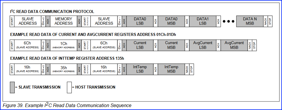
In my opinion, the MAX17320's data sheet provides incorrect (or at least incomplete) information when discussing the I2C Protocols on pages 160 through 163. For example, consider Fig. 1 below, which shows Fig. 39 from page 161 in the data sheet:

enter image description here Fig. 1

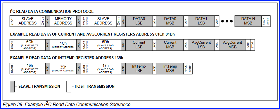
The figure's top element correctly shows the 7-bit device address field and the 1-bit read/write field as two distinct/separate fields. It is very important to recognize that the read/write bit field IS NOT part of the 7-bit device address. However, both of the EXAMPLE elements in Fig. 39 imply the address field and the read/write field are merged into one 8-bit field whose value is 16h for write, and 17h for read. I strongly suspect this is incorrect. More specifically, I think the correct way to draw Figure 39 is as shown in Fig. 2 below:

enter image description here Fig. 2

In Fig. 2, note the addition of the read/write bits and the updated slave address values in both of the EXAMPLE elements.

If the 7-bit device (slave) address is 16h, and if that address is combined with the read/write bit to form an 8-bit value, the resulting 8-bit values for WRITE and READ would be:

                                     vvvvvvv--- device address bits
WRITE: (0x16<<1) & 0xFE = 0x2C   ; 0b00101100
READ:  (0x16<<1) | 0x01 = 0x2D   ; 0b00101101
                                            ^-- read/write bit

Note that these 8-bit values are not 0x16 and 0x17, as indicated in Figure 39 within the data sheet (see Fig. 1).

For what it's worth, let's assume figure 39 in the data sheet is correct as shown in my Fig. 1, and therefore the combined 8-bit values for the 7-bit slave address with the read/write bit are as follows:

                   vvvvvvv--- device address bits
WRITE:  0x16   ; 0b00010110
READ:   0x17   ; 0b00010111
                          ^-- read/write bit

That would mean the device's slave address is in fact 0b0001011 or 0Dh, which contradicts table Table 115 on page 159 of the data sheet, for example, which states the I2C slave addresses are 6Ch and 16h:

enter image description here Fig. 3

\$\endgroup\$
9
  • \$\begingroup\$ The chip uses address 0x16 for write and 0x17 for read. That's already in 8-bit notation. Therefore, your code shifting the 0x16 address by one bit to left for API must be incorrect. If API takes 8-bit notation, no shift needed, if API takes 7-bit notation, shift to right is needed to convert 0x16/0x17 to 7-bit address. \$\endgroup\$
    – Justme
    Commented Jun 18, 2023 at 7:39
  • \$\begingroup\$ @Justme, I looked at multiple code examples and they all left shift the I2C device address argument by one bit; so, that's why I left left shifted the device address argument. The first seven bits sent by the master are the device address, e.g., 0b0010000 for 0x16. The eighth bit is the Read/Write (1/0) bit. So, 0b00100000 (Write) and 0b00100001 (Read). And looking at the source code that implements function HAL_I2C_Mem_Read(), I'd argue that the calling function must left shift the device address by one bit, as shown in the examples (and in my example). \$\endgroup\$ Commented Jun 19, 2023 at 18:59
  • \$\begingroup\$ Argue as you wish, but the datasheet clearly says write address is 0x16 and read address is 0x17, so they are 8-bit address notations that already include the R/W bit and are not supposed to be shifted left any more. STM32 HAL uses 8-bit notation. If you want to use the 7-bit notation without R/W bit, then address is 0x0B and must be shifted left by 1 for STM32 HAL. Also, 0x16 is 0b00010110 and 0x17 is 0b00010111. HAL handles clearing and setting the LSB bit for R/W as required. \$\endgroup\$
    – Justme
    Commented Jun 19, 2023 at 19:10
  • \$\begingroup\$ Data sheets are not always correct. I've done this for 40+ years and I've seen countless errors in data sheets during that time. For example, I suspect figures 39 through 42 on pages 161 through 163 in the data sheet are flawed/incorrect. Hence my recommendation to use an oscilloscope or a logic analyzer to monitor the signals on the SDA and SCL lines as the software invokes function HAL_I2C_Mem_Read(). This will help the OP verify that device address 0x16 is being sent in the first seven bits, and that 0/1 (write/read) is sent in the eighth bit. \$\endgroup\$ Commented Jun 19, 2023 at 19:36
  • \$\begingroup\$ And thank you for pointing out that the correct bit pattern for address 0x16 is 0b0010110 and not 0b001000 as I'd stated. With this in mind, the oscilloscope / logic analyzer should capture these bits on the I2C bus whenever the master is addressing the slave device: 0b00101100 (0x2C) (write) and 0b00101101 (0x2D) (read). \$\endgroup\$ Commented Jun 19, 2023 at 20:00

Your Answer

By clicking “Post Your Answer”, you agree to our terms of service and acknowledge you have read our privacy policy.

Not the answer you're looking for? Browse other questions tagged or ask your own question.