0
\$\begingroup\$

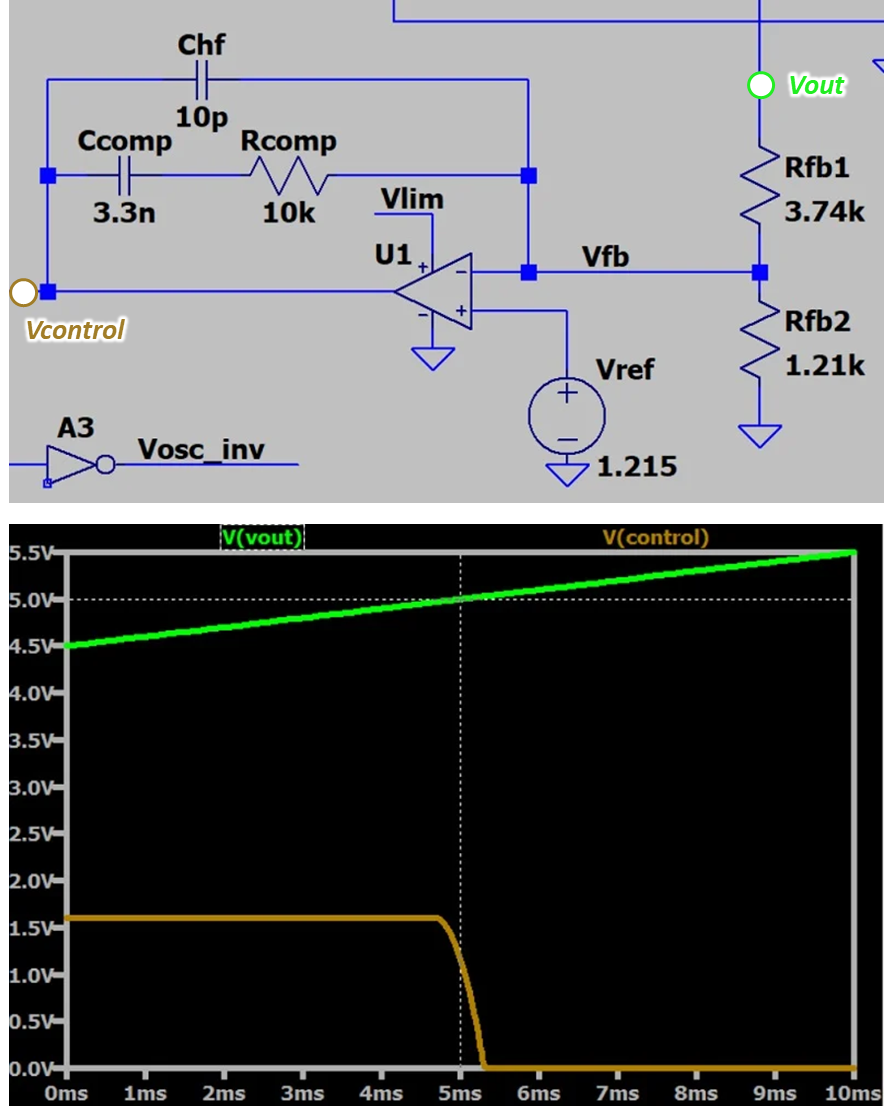
I'm simulating the "voltage error amplifier circuit" referenced from this article

In the article, "Vcontrol" will drop to zero when "Vout" is larger than the reference voltage (1.215 [V] here)

But i'm wasn't being able to replicate the result from the above article

The simulation result and circuit from the article are shown below enter image description here
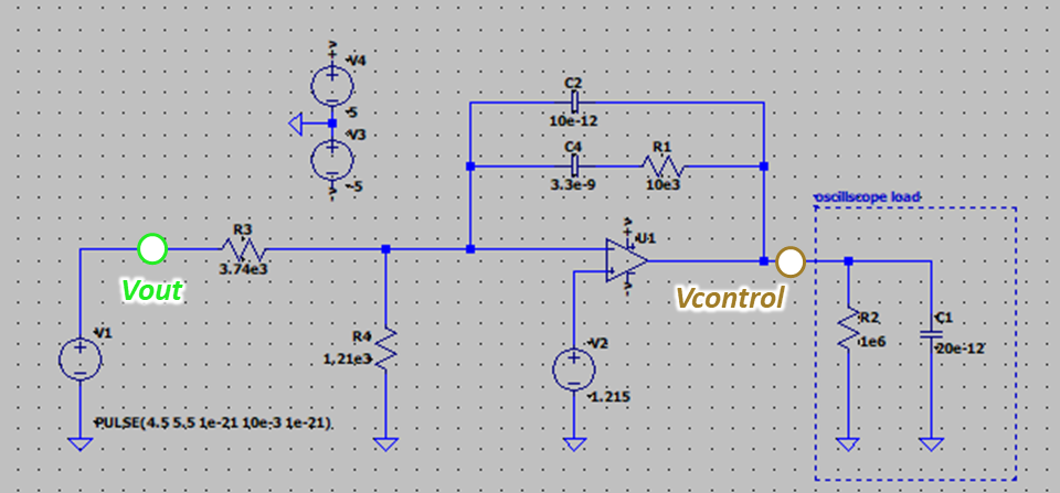
Mine is shown below (Simulating in LTspice)

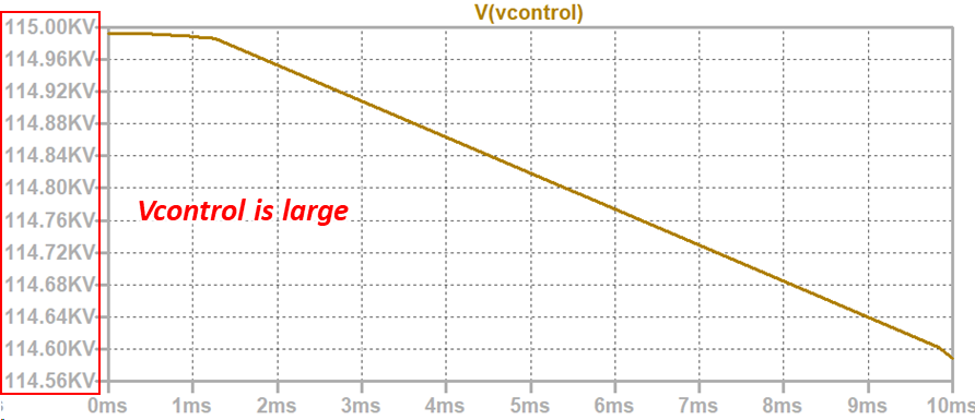
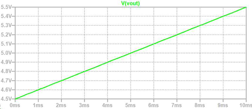
enter image description here enter image description here enter image description here

The control voltage (Vcontrol) is hundreds of kilovolts, which is quite not reasonable

My questions are

a) How could I modify my circuit to meet the same result as in the article?

b) Is there a design criterion to choose the feedback passive elements?

Thanks!

2024/03/18 UPDATE

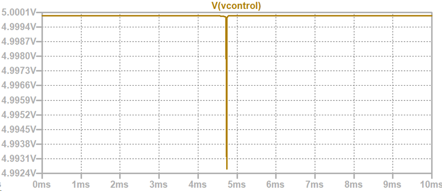
After changing the op model to "UniversalOpAmp3" from @Fabio Barone's suggestion, the output "Vcontrol" became more reasonable in amplitude, but the result is still different from the article. enter image description here
2023/03/19 UPDATE

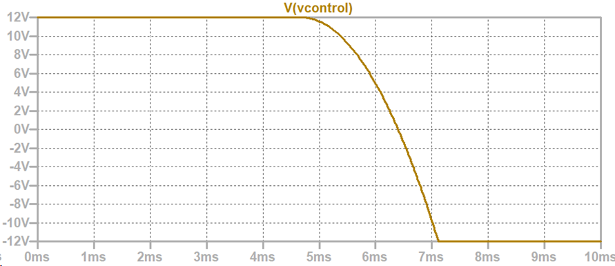
After correcting the voltage supply polarity from @Fabio Barone's suggestion, the result looks normal now, below is the result for two changes

1.Change the polarity of V3, which is the main reason that this circuit didnt function normally. enter image description here
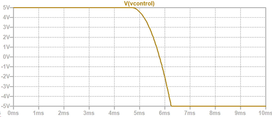
2.Change the supply rail from +/-5 [V] to +/-12 [V] enter image description here

\$\endgroup\$
4
  • \$\begingroup\$ This circuit is an integrator ... You must use the whole circuit to simulate it ... \$\endgroup\$
    – Antonio51
    Commented Mar 18 at 7:08
  • \$\begingroup\$ Hello, may I ask the reason for using whole circuit to simulate it? \$\endgroup\$
    – Jack Huang
    Commented Mar 18 at 7:33
  • \$\begingroup\$ As you use it, with your Pulse definition, it should be fast "saturated" ... \$\endgroup\$
    – Antonio51
    Commented Mar 18 at 8:01
  • \$\begingroup\$ @Antonio51 Sorry, what do you mean "fast saturated" \$\endgroup\$
    – Jack Huang
    Commented Mar 18 at 8:15

2 Answers 2

1
\$\begingroup\$

What is the model name of the component you used for U1? If it is a simple model, such as "UniversalOpAmp", then be aware that it does not have any limits for output voltage or current. I suggest you use the model called "UniversalOpAmp2", which is a simple model that implements basic limits for output voltage, and output current.

The help file will explain this. Search for "Universal OpAmp Models" in the help.

Edit: other changes:

  1. V3 polarity is incorrect, change value to positive.
  2. Opamp needs supply rails of +12, -12, change V3 & V4 to +12 each.
\$\endgroup\$
4
  • \$\begingroup\$ Hello, yes, I'm using "UniversalOpAmp" model. I didn't pay much attention to them before (my bad), after changing it to "UniversalOpAmp2", the "Vcontrol" became smaller, but the result is still not correct. Do you have any further suggestions? Thank you in advance! \$\endgroup\$
    – Jack Huang
    Commented Mar 18 at 8:01
  • \$\begingroup\$ Please refer edits to my answer after your comments. \$\endgroup\$ Commented Mar 18 at 22:02
  • \$\begingroup\$ Hello, the circuit works now but I still have a little question. The "Vcontrol" shown in the article is limited from about 1.6 [V] to 0 [V], does this imply that the "Vlim" the author used to supply the op is 1.6 [V]? \$\endgroup\$
    – Jack Huang
    Commented Mar 19 at 1:47
  • \$\begingroup\$ Possibly, but not necessarily. The circuit in your question is not the same as that "shown in the article"; yours does not show all the details of the power converter. It could be that the range of 0 to 1.6V is simply the range of the timing ramp used to generate the PWM, in which case the reference that is compared to the timing ramp should be limited to the same voltage range as the timing ramp. \$\endgroup\$ Commented Mar 19 at 3:04
0
\$\begingroup\$

Here is what you get (with modification to slow down waveform ...)
C2 made 10 nF in place of 10 pF.

enter image description here

\$\endgroup\$
4
  • \$\begingroup\$ Hello Sir, thank you for your effort! But I am curious about this circuit functioning as a controller compared to a Vset (1.215 here) in the automatic gain control circuit. There will be a voltage control resistor followed by the output of this circuit. Is it possible to remake the result (Vout, Vcontrol) shown in the article using this circuit? \$\endgroup\$
    – Jack Huang
    Commented Mar 18 at 10:03
  • \$\begingroup\$ To see if this is ok and works, you must complete all the circuit ... which can be a little "long" to make ... except that the schematic in the link is not complete. It does not say "how" CMPR and PWMr are "tied". I'm searching for the next article ... \$\endgroup\$
    – Antonio51
    Commented Mar 18 at 10:07
  • 1
    \$\begingroup\$ I found next article ... allaboutcircuits.com/technical-articles/… with the "complete" schematic. \$\endgroup\$
    – Antonio51
    Commented Mar 18 at 10:19
  • \$\begingroup\$ Thank you for your advice, Sir. The problem is solved, it turned out that I used the wrong polarity voltage to drive the opamp in my circuit. \$\endgroup\$
    – Jack Huang
    Commented Mar 19 at 2:26

Your Answer

By clicking “Post Your Answer”, you agree to our terms of service and acknowledge you have read our privacy policy.

Not the answer you're looking for? Browse other questions tagged or ask your own question.