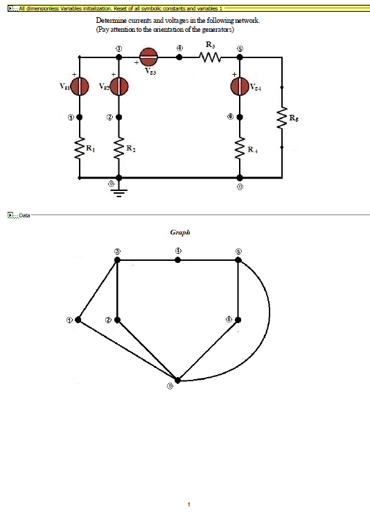
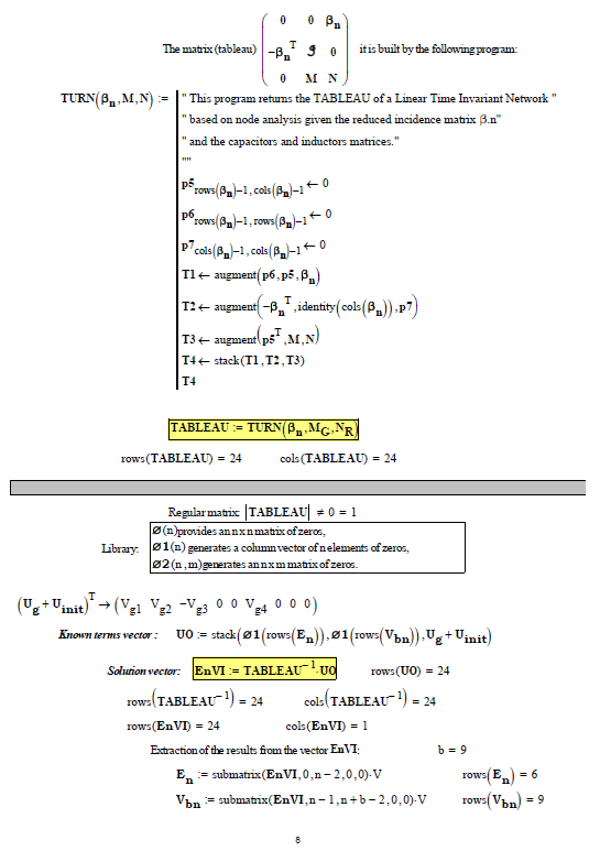
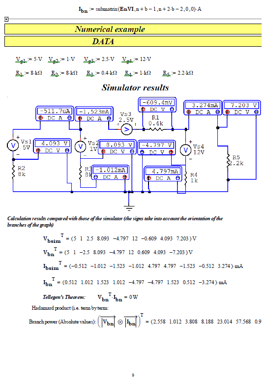
I'm preparing for an upcoming exam in electrical engineering and came across this task. My question is: Which method is best for this? I think the superposition principle would be very complex, right? And is there a simulator that can calculate the entire network that you can recommend to me? I saw an answer to a similar question here where all the network analysis methods were solved in the simulator, but I don't know what it's called. I would be grateful for any tips. Many thanks in advance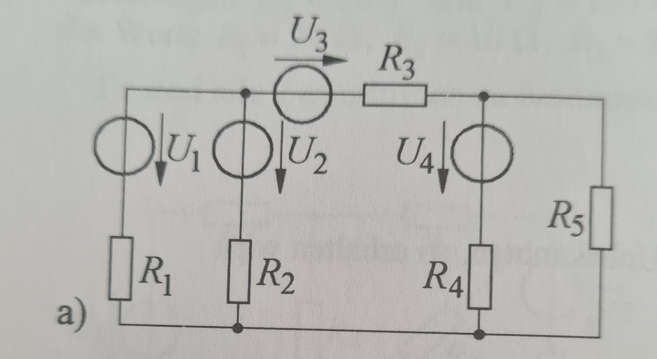
-
\$\begingroup\$ This circuit can be solved in the head when using source transformation without using any circuit simulator. As for the simulator you can try use on this falstad.com/circuit/circuitjs.html or LTspice. \$\endgroup\$– G36Commented Mar 28 at 14:36
-
\$\begingroup\$ It comes down to mesh or nodal, even if you choose to use or not use superposition. \$\endgroup\$– DKNguyenCommented Mar 28 at 14:36
-
\$\begingroup\$ Maybe the simulator you saw was microcap<-- click on full CD \$\endgroup\$– Andy akaCommented Mar 28 at 14:51
-
1\$\begingroup\$ You haven't indicated in your question what needs to be solved. \$\endgroup\$– Andy akaCommented Mar 28 at 15:29
-
\$\begingroup\$ Oh, I should find all currents in the circuit. \$\endgroup\$– OmarCommented Mar 28 at 17:02
3 Answers
question and answer
I'm preparing for an upcoming exam in electrical engineering and came across this task. My question is: Which method is best for this?
There are these commonly applied techniques (for KCL analysis):
- Select an optimal node as ground. Sometimes, this requires a little thought and/or experience. So practice this skill.
- Once ground is selected, consider each branch in the circuit composed of series 2-terminal devices that can be re-ordered freely and see if re-ordering any of them might help simplify the circuit.
- For cases where voltage sources have one end tied to ground (and this is partly why you need to learn how to select an optimal ground in #1) or can be re-arranged so as to have one end tied to ground, get rid of the voltage source itself and just label the non-ground node with the associated voltage.
- Remove all wires that bus from the non-ground nodes of voltage sources from #3 and use labels, instead. Wires crisscrossing all over the place in a schematic just get in the way of understanding. Labels are clear. Wires are distracting.
- Split current sources into two halves, each half either leaving a node or entering another node, from empty space (nowhere.) Current sources are infinite impedance so showing a connection between two nodes can serve to distract.
- If it doesn't cause the loss of important nodes or the meaning of important currents, perform any easy source transformations involving Norton to/from Thevenin or where several parts can be combined into fewer parts with equivalent replacements. (But keep in mind that if you need to know a node voltage or a branch current and you eliminate either in the process then the results won't help.)
- If the work must be handled by hand, on paper, and without the aid of a computer to do simultaneous solutions then make sure you understand how to set up the linear equation matrix and use Cramer's Rule for solving (and/or learn to diagonalize.) This works both symbolically and/or using numerics, too.
- Learn how to form a set of linear equations using KCL (nodal.)
KCL is generally easier to use in setting up equations for larger schematics, I think. So I tend to avoid KVL (mesh.) However, there are times (especially when parts aren't just 2-terminal, but include 3 or 4 terminal devices) when KVL may be needed.
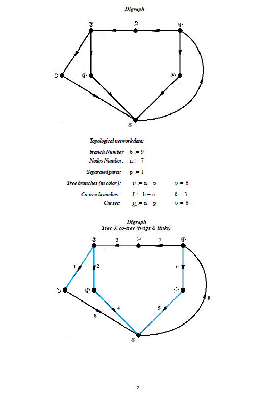
I gravitate towards KCL because complex schematics may be more difficult when trying to work out the exact right number of meshes for KVL purposes. This can be handled robustly using directed graph theory. One of the null-spaces tells you with precision and perfection a minimum set of meshes. But you have to learn to massage the directed graph to get the null-space out of it. And that's a different topic.
I think the superposition principle would be very complex, right?
I find it more painful than just using KCL and solving when I have a computer handy. But it's another technique and you should develop a skill using it, as well. Especially if you may be required to do hand-work.
And is there a simulator that can calculate the entire network that you can recommend to me? I saw an answer to a similar question here where all the network analysis methods were solved in the simulator, but I don't know what it's called. I would be grateful for any tips. Many thanks in advance
In this case, there are a number of relatively good simulators that are available now without cost. You should pick one and get familiar with it. I use LTspice. But it is shy on parts that aren't made by Linear. Other simulators are strong on commercial part models, but may be weak in other ways. Search around for commentaries and try a few of them on some simple problems to see which of them may serve you better.
You should also learn Python and how to use SymPy and SageMath. There's a bit of a learning curve to getting things set up. But they are free, powerful, and worth your time. Together you can get both numerical and symbolic solutions with ease. They serve different purposes (solving sets of equations, for example) than a Spice simulator, though they can at times also reproduce Spice simulation results. But they supplement what Spice can do and expand the range of problems you can work on and solve. So worth some time, when you may find some.
example
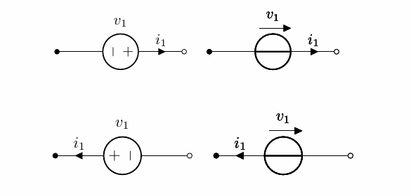
I've never been able to figure out some of the European conventions with respect to your voltage sources. I've seen both of the following:
I guess it depends on whether or not you live in Italy, Spain, or somewhere else? I have just given up on it and am usually forced to guess the meaning, lacking additional information. Just FYI.
This just means I don't know what you wrote in your example. Not exactly.
That said, let's look at the following similar (but not identical) schematic:
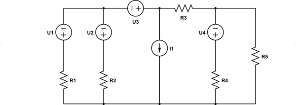
simulate this circuit – Schematic created using CircuitLab
I might do the following to it:
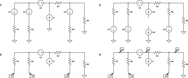
Step 1 selects a ground node. Step 2 breaks up the current source and re-arranges some serial branches to place the voltage sources so that one end is grounded. Step 3 removes a useless current source to ground and replaces the voltage sources with labels. (Note marking them negatively.) Step 4 adds labels to some remaining nodes of interest.
Recognizing that \$U_x\$ and \$U_y\$ form a super-node, with \$U_y=U_x+U_3\$, KCL can now be readily applied:
$$\begin{align*} \frac{U_x}{R_1}+\frac{U_x}{R_2}+\frac{U_y}{R_3}+I_1&=\frac{-U_1}{R_1}+\frac{-U_2}{R_2}+\frac{U_z}{R_3} \\\\ \frac{U_z}{R_3}+\frac{U_z}{R_4}+\frac{U_z}{R_5}&=\frac{U_y}{R_3}+\frac{-U_4}{R_4} \end{align*}$$
(Above \$U_1\$, \$U_2\$, \$U_3\$, and \$U_4\$ are all positive values representing the magnitude of each source. But note that I had to negate \$U_1\$, \$U_2\$, and \$U_4\$ when replacing the voltage supplies with labels, as the negative end was the non-grounded end.)
That's it. Replace \$U_y\$ as appropriate above and solve for \$U_x\$ and \$U_z\$.
This should be explained in a course on circuit analysis.
The node voltage method and the loop current method will result in just enough equations to solve a circuit. Loop current is limited to planar circuits.
You can write a bunch of KVL, KCL equations nonsystematically and mix them up and eventually you might find the right answer.
Superposition, source conversion, series/ parallel, and some other tricks may result in a faster solution to some circuits.
Usually we look at a circuit, and if there is no obvious way to do it faster then resort to the systematic methods.
-
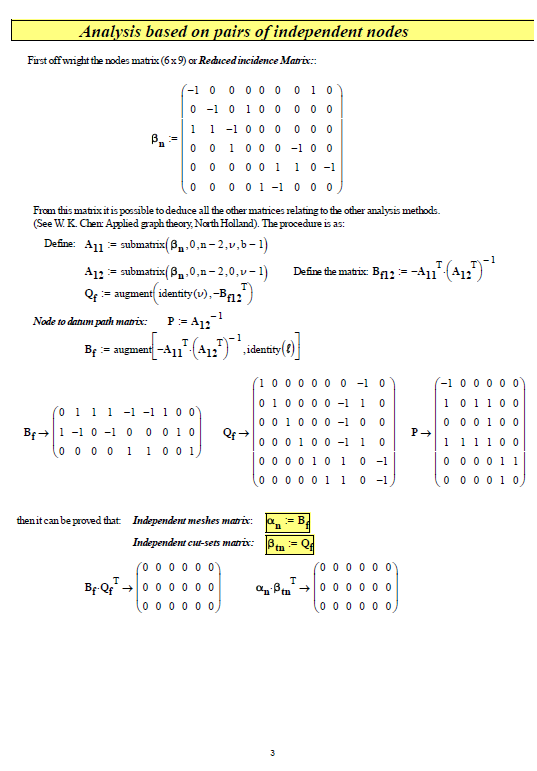
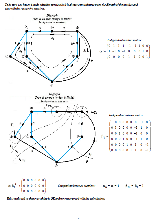
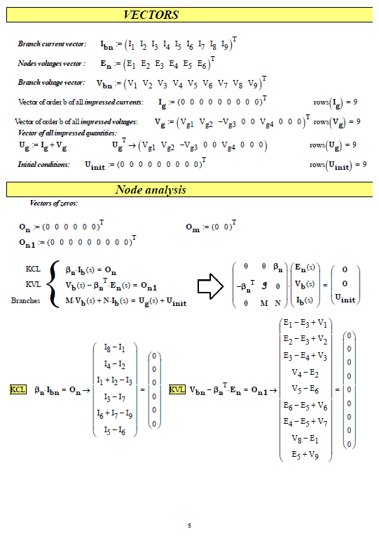
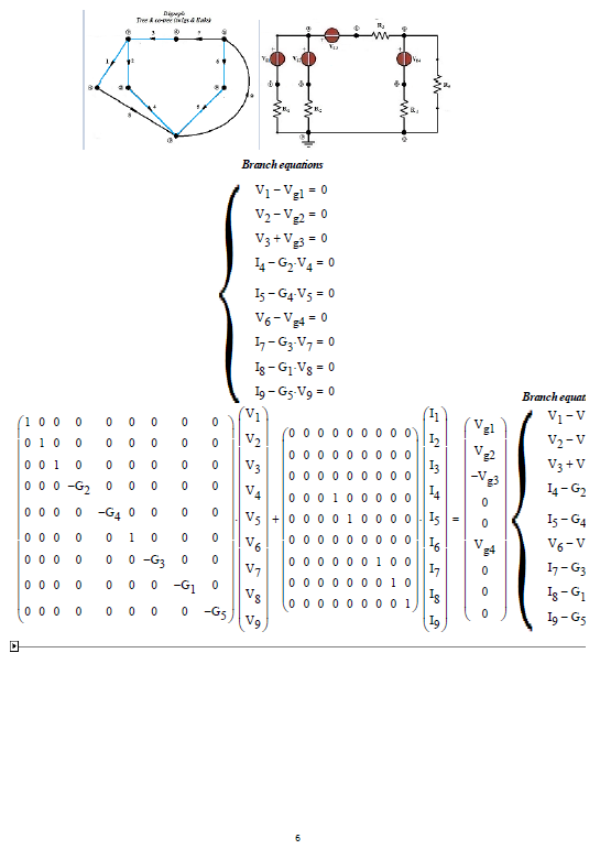
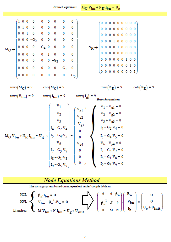
\$\begingroup\$ The simulator only serves you to verify the calculations made with pen and paper and it is of no use during the exam, It is forbidden to use computers in a written exam session and even more so in an oral one. During the exam you must rely only on what you have learned by studying from notes if taken well or from an electrical engineering text. If an in-depth analysis is carried out, it is found that the matrix of independent node pairs is sufficient from which to deduce the other matrices, i.e. independent meshes and independent cutting sets. The superposition method is the slowest . \$\endgroup\$ Commented Mar 28 at 18:36
-
\$\begingroup\$ @franc Exactly, of course I will only use the simulator during the preparation period to check my results. I think I saw your answer in the similar question about the superposition principle and you wrote a very helpful answer. Can you please tell me which simulator you used? That would be very nice. Thank you in advance \$\endgroup\$– OmarCommented Mar 28 at 21:59
-
\$\begingroup\$ @Omar I use the CircuitMaker simulator. of the late nineties. However, any simulator is fine. StackExchange's "Schematic" of "ElectricalEngineering" is also excellent. My method using TABLEAU is still in experimentation and I deduced it from Chua/Desoer/Kuh's text "Linear and nonlinear circuits" by McGraw Hill. \$\endgroup\$ Commented Mar 29 at 7:29
-
\$\begingroup\$ Ok, thank you. So you used the circuit simulator in the task with superposition and it performed all the network analysis procedures, right? \$\endgroup\$– OmarCommented Mar 30 at 8:05
@Omar No! the simulator only provides the results as in the last photo! the method it uses is not accessible. You can't get the calculation procedure, it's against all software trading logic.

