2
\$\begingroup\$

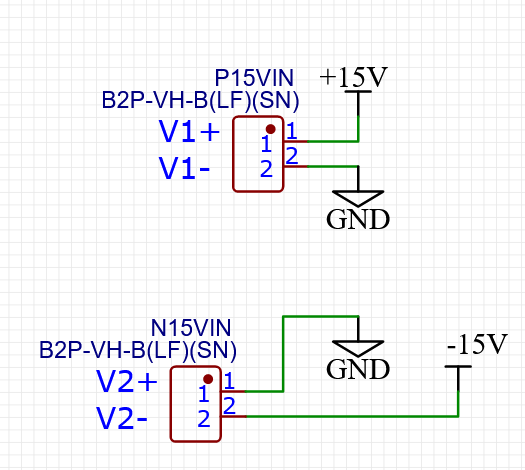
I am using two identical Meanwell LRS-150-15 power supplies to produce +15VDC and -15VDC compared to ground. My ground is tied to earth. The setup with its connectors and nets is represented in the image bellow:

enter image description here

Is this setup theoretically safe? Is there a risk current might flow in an undesired way without integrating diodes? Should I place diodes on the -15V net as well as the +15V one?

\$\endgroup\$
5
  • 1
    \$\begingroup\$ What will diodes bring to the party? Please show how you considered using them. \$\endgroup\$
    – Andy aka
    Commented May 7 at 13:41
  • 1
    \$\begingroup\$ For those interested, here's the datasheet. \$\endgroup\$ Commented May 7 at 13:41
  • \$\begingroup\$ Andy, I am wondering if perhaps the current might flow in an unintended way given the two power supplies tied via their V1- and V2+, the diodes would act as a protection against that. I am not sure where I would place the diodes \$\endgroup\$
    – Tommy95
    Commented May 7 at 13:45
  • \$\begingroup\$ You have two 150W power supplies. If one of them takes longer to turn on and you have a load passing 10A between +15V and -15V, you might be applying +15V to -15V output. And 10A. It might be a good idea to state what load you need that requires 300W of dual supplies and making them with two discrete supplies instead of one? \$\endgroup\$
    – Justme
    Commented May 7 at 13:45
  • \$\begingroup\$ Thanks Justme. Nothing will be powered between -15V and +15V. A part of the design requires to be power by +15V compared to ground, and another one -15V compared to ground. \$\endgroup\$
    – Tommy95
    Commented May 7 at 13:49

1 Answer 1

8
\$\begingroup\$

What you are about to do is basically connecting two isolated outputs in series.

The outputs are isolated from mains and the mains ground (PE) so you are allowed to connect them in series.

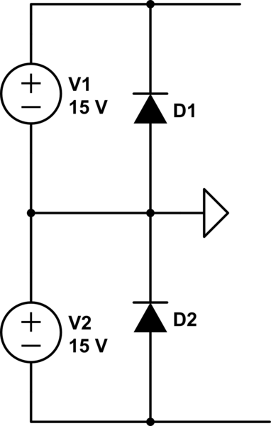
One thing to consider here is that, even if they are of the same brand and model they are not identical, so the startup behaviour might be different. This means that one can start before the other so one may see negative voltage across its outputs. Even if this usually happens for a very short time (a few milliseconds) still may hurt something inside. To prevent that, you may place reverse diodes across each output. Just in case...

schematic

simulate this circuit – Schematic created using CircuitLab

\$\endgroup\$
3
  • \$\begingroup\$ Cheap insurance for what-if scenarios. \$\endgroup\$
    – winny
    Commented May 7 at 14:23
  • \$\begingroup\$ Thanks a lot! Would you have any recommenced rating for the diodes? Should they be able to rectify as much current as the power supply can at most deliver? \$\endgroup\$
    – Tommy95
    Commented May 7 at 14:56
  • 2
    \$\begingroup\$ @Tommy95 They should be suggested by the manufacturer/designer so I'd check the app notes (if available) first. If you can't find anything then 1) the reverse breakdown voltage should be higher than the individual output and 2) the avg current rating doesn't have to be at least the rated output current, but the diode should allow that level of current during the startup time of individual supply, which is given as 30ms in the datasheet. So you may need to check the SOA and other graphs in the datasheets if you don't want to use a 10-Amp diode. \$\endgroup\$ Commented May 7 at 16:29

Your Answer

By clicking “Post Your Answer”, you agree to our terms of service and acknowledge you have read our privacy policy.

Not the answer you're looking for? Browse other questions tagged or ask your own question.