1
\$\begingroup\$

EDIT: Additional Information below original post...

Looking for a 360 degree servo motor that has adjustable control for timing of steps
(or at the least timing per full oscillation) and can support (via vertical shaft) at
least 30 pounds of weight overhead (imagine a oscillating tower fan where the base is
the motor and the fan is the 30 pound weight with a vertical shaft at least 4 feet in
length). Any suggestions for where to look for a baseline to mod or an off-the-shelf
solution?

Thanks for assisting in directing my ongoing efforts to build my prototype, peeps :)

I still have some primary concerns and questions unanswered in regards to the gearing, controls, etc for the oscillating motor and will continue those in more specific "Questions" posted as I think of them. I will post some google sketchup images of examples, as well. Thanks again and looking forward to hacking this project to completion :D

Google Sketchup Prototype:

I guess I'll fill out the images once I have 10 frickin points. :P

img src="http://goo.gl/fZykD" width="912" height="445" title="Google sketchup prototype Revision 1"

img src="http://goo.gl/kVBAi" width="1024" height="498" title="Revision 2"

\$\endgroup\$
5
  • \$\begingroup\$ would a stepper motor work for you instead of a servo? \$\endgroup\$
    – jsolarski
    Commented Apr 6, 2011 at 7:17
  • \$\begingroup\$ I imagine a stepper motor would work (hence the step control statement above) however I don't have a use for a holding torque (which from my understanding is a significant selling-point of the stepper motors) so was leaning towards DC servo motors. As I'm not a motor expert this could obviously be a misdirected effort on my part... have any enlightened suggestions to help me out? :D \$\endgroup\$
    – Daerk
    Commented Apr 6, 2011 at 8:48
  • \$\begingroup\$ You will need to provide performance specs before anyone will be able to give you a reasonable answer. How many degrees do you need to rotate your load, and in how much time? \$\endgroup\$
    – Dave
    Commented Apr 6, 2011 at 16:04
  • \$\begingroup\$ Roger that. Ok, Essentially I am rotating three 6 and a half pound 24 inch long light fixtures attached to a 3 5/64" equilateral triangle vertical mount shaft with an extension aluminium tube shaft from it's base for the motor to couple to. I would prefer the ability to oscillate a full 360 degrees over a variable timeframe (remotely controlled via dial/switch/etc), fastest at 1 full rotation about every 1 second and slowest at 1 full rotation every 10 seconds. The wooden shaft is about 30 inches in height and is poplar wood. As of right now the 3/8" width aluminium shaft is 6" long. \$\endgroup\$
    – Daerk
    Commented Apr 6, 2011 at 22:32
  • \$\begingroup\$ Forgot to mention in my last post, that eventually this triangular shaft will be replaced with a square wooden shaft and a fourth light added of the same weight. Also, if anyone could possibly assist with finding a rotary slip ring assembly that would support four 120v~277v 50/60Hz lights through it rotating along with the shaft that'd be helpful as well ;) \$\endgroup\$
    – Daerk
    Commented Apr 7, 2011 at 0:20

2 Answers 2

4
\$\begingroup\$

Unless you go with something big like a 1/2hp motor, you're going to have to build this yourself. The bearings on a small servo or stepper won't support that kind of load. You have to deal with the vertical thrust load of 30 lbs and then any torque caused by the load - motor axis not being perfectly vertical! You will need to build a base and a vertical support with bearings to carry the shaft. A couple of 2x4's would do it just fine. Or you could start with a floor lamp and toss the lamp head part.

Having said that, once the load is properly supported, it shouldn't be too hard to turn so a size 23 stepper motor will probably do it just fine.

How thick is the axis you want to turn? Maybe I can offer some suggestions on where to get the parts you need.

\$\endgroup\$
3
  • \$\begingroup\$ Ouch. Trying to not have to custom build it (would much rather just use something off-the-shelf). I think I could get by with as small as 3/8" shaft of aluminium tube that's embedded into my wooden shaft (equilateral triangle 3 5/64" wide, 30 inches tall.). The triangular wooden shaft has 3 vertical tube-light fixtures mounted to it, and the shaft needs to rotate 360 degrees then oscillate back so that each light exposes the vertical polycarbonate aquarium tubes surrounding the shaft. Here's a quick google sketchup: goo.gl/fZykD \$\endgroup\$
    – Daerk
    Commented Apr 6, 2011 at 18:08
  • \$\begingroup\$ Doesn't look so bad. If you can put a shaft on the top of the triangular part and mount a bearing on that top plate and another on the bottom, that should take care of proper support. \$\endgroup\$
    – lyndon
    Commented Apr 7, 2011 at 2:03
  • \$\begingroup\$ Good, already planned on a shaft on top freely spinning. Had planned on maybe using some ball bearing coupling on the top and I guess I could do the same for the bottom, then just have the motor turning the shaft from the bottom where the shaft extends beyond the bottom supporting ball bearing. Now the question is what type of motor, and gearing, and controller, and potentiometer, (etc) do I need to get this puppy rolling... \$\endgroup\$
    – Daerk
    Commented Apr 7, 2011 at 2:51
1
\$\begingroup\$

As lyndon said -- the bearings inside a typical motor won't support that kind of axial thrust. Not to worry though -- the bearings inside the motor don't need to support any axial thrust if you set up your system with a separate thrust bearing at the bottom and possibly the top of the shaft.

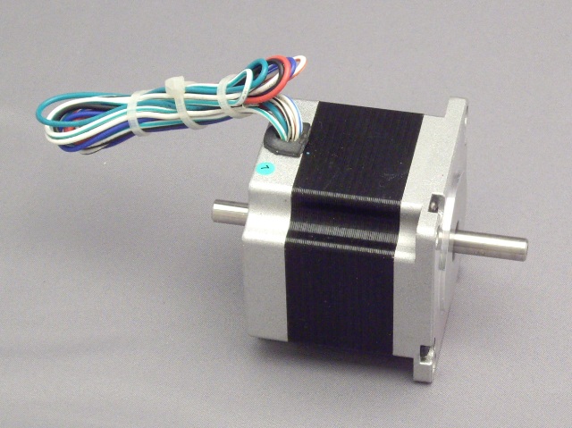
Perhaps the simplest approach is to use a motor where the shaft exits both ends of the motor something like this one:

motor with axis through and extending from both ends

A thrust bearing holding up the shaft exiting the bottom of the motor can hold up the full weight of all the stuff you have rigidly attached to the shaft exiting the top of the motor.

Perhaps the next-simplest approach is to put a thrust bearing at the bottom and a skate bearing (or another thrust bearing) at the top, with a concentric wheel somewhere between, and use a V-belt between that wheel and the motor mounted next to your rotating assembly.

\$\endgroup\$
3
  • \$\begingroup\$ I'm noticing almost everyone is recommending using a thrust bearing at the BOTTOM of the rotating axle, any particular reason? I was hoping to use the thrust bearing assembly at the top to reduce the complexity of the bottom rotating joint so I could work out a solution to passing the electric functionality I need along to the shaft-mount. I guess I could pass the power via the top, but I need to nail down these design elements ASAP. So, Top or bottom mounted thrust bearing to handle load? :) \$\endgroup\$
    – Daerk
    Commented Apr 9, 2011 at 13:27
  • \$\begingroup\$ The primary load is the 30 lbs weight that will be pushing the shaft down into the base, so the thrust bearing is at the bottom to support this load. Another (radial) bearing should be at the top to hold the other end of the shaft and let it rotate. \$\endgroup\$
    – lyndon
    Commented Apr 10, 2011 at 2:36
  • \$\begingroup\$ I suppose it is possible to use a thrust bearing at the TOP of the rotating axle that holds up everything hanging from it. If you then put your motor near the top, then perhaps you wouldn't need anything touching the bottom. \$\endgroup\$
    – davidcary
    Commented Apr 17, 2011 at 5:24

Your Answer

By clicking “Post Your Answer”, you agree to our terms of service and acknowledge you have read our privacy policy.

Not the answer you're looking for? Browse other questions tagged or ask your own question.