4
\$\begingroup\$

I'm looking at the data sheet for an Analog Devices LTC7149 step-down regulator. On the first page there's a "Typical application" circuit diagram that shows a capacitor on the VOUT- output that's labelled "22µF × 2".

Does this mean that the circuit should contain two 22 µF capacitors (presumably in parallel), and not just the one that is shown on the drawing?

  • Why are there two capacitors? Perhaps because 44 µF isn't a common value, so 2× 22 µF in parallel provides this?
  • Why not just draw two capacitors on the diagram? My guess is that it's simply to save space, as the figure is quite busy.

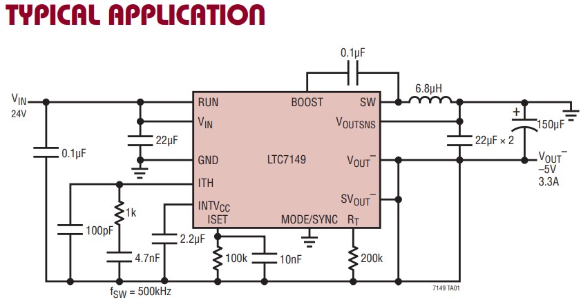
Circuit diagram from the data sheet

\$\endgroup\$
3
  • \$\begingroup\$ Note that it's also in parallel with an additional 150µF capacitor. \$\endgroup\$ Commented Aug 24 at 6:32
  • \$\begingroup\$ @pipe It should be changed, such details matter. However it's not even the "x 2" you mention, it's "× 2" -- a multiplication sign, not a letter x. \$\endgroup\$
    – Dan Mašek
    Commented Aug 24 at 12:51
  • 1
    \$\begingroup\$ As everyone reports, it does mean 2 of them. What doesn't seem to be mentioned is that there are probably specific requirements for where they are placed. I suspect one of them, and the one on Vin, are to be placed as close to the pins as possible. Read the datasheet in detail. \$\endgroup\$
    – David G.
    Commented Aug 25 at 23:20

4 Answers 4

7
\$\begingroup\$

Yes, that means 2 22uF capacitors in parallel. For your first follow-up question check out Dan's answer to this question, although there are also many articles and explanations on this topic out there that I would recommend reading. For your second follow-up, yes it is probably just to save space and make the circuit less busy.

\$\endgroup\$
7
\$\begingroup\$

Yes it is 2 capacitors in parallel. You could say it is because 44uF is not available, but 47uF generally is.

The reason for 2 in parallel is to reduce ESR and, more importantly, ESL of the capacitors.

It could also be to reduce ripple currents in the cap to keep it at some safe level.

In my opinion, the input capacitor (VIN,GND) should be configured as such, as well.

\$\endgroup\$
1
  • 2
    \$\begingroup\$ 22uF capacitors are also pretty common. I don't think using a single 47uF would be the best design choice for thermal reasons as well. \$\endgroup\$
    – Colin
    Commented Aug 23 at 14:36
7
\$\begingroup\$

Yes, it's two 22uF capacitors in parallel.

Depending on when the document was written, two 22uF ceramic capacitors may have had better characteristics such as capacitance at operating voltage, been more available (available at all) or cheaper than a single 47uF capacitor.

It's just drawn that way to keep things simple.

\$\endgroup\$
1
\$\begingroup\$

Why not just draw two capacitors on the diagram?

Mostly because it'd just make it busy while conveying not all that much new information. When schematic diagrams are free-drawn (vs using EDA), the draftsman/illustrator has some leeway to make them more readable.

Decades ago, when companies were transitioning from hand-drafted schematics to computer drafting and EDA, they developed in-house software that provided a lot of the same shorthand notation as was common in hand-drafted schematics. As the years passed, the art of the schematic drafting and the in-house software gave way to cost reduction and "rationalization". Thus everyone ended up using more-or-less the same software, just written by different companies.

\$\endgroup\$

Your Answer

By clicking “Post Your Answer”, you agree to our terms of service and acknowledge you have read our privacy policy.

Not the answer you're looking for? Browse other questions tagged or ask your own question.