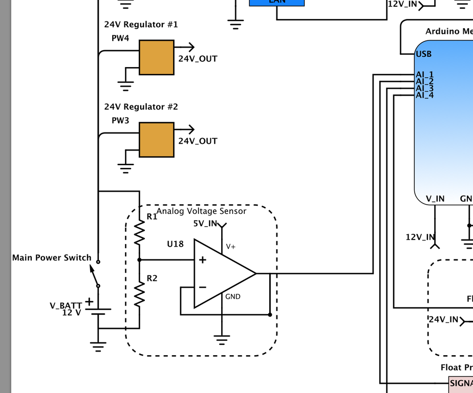
Current limiting could be provided by the resistors themselves. If you made a 3:1 divider from a 10k and a 5k resistor, 15 volts on the input would translate to 5 volts on the output. Assuming the lower resistor (5k) went open circuit, the circuit would try to produce 15 volts but be limited to something like 1mA due the the Arduino's input schottky diodes and the 10k resistor.
Simpler is better but if you have a worry that the voltage could rise significantly higher than 15 volts then make the resistor divider a greater ratio. As regards the op-amp providing current limiting this is not really the case unless it is run from the same supply as the arduino. Another problem with the op-amp is that even a rail-to-rail device is not truly rail-to-rail and you might lose 50mV top and bottom.
My advice, work out the input voltage limits and keep it simple with a resistor divider and no op-amp. Add a 100nF across the 5k resistor and any glitches that may be on the battery supply will be largely killed-off by the cap.
Another point is that you can't make the resistors too large because the spec for the ADC on the arduino suggests 10k is the maximum input resistance to accurately measure a voltage source. This is significantly helped by the 100nF capacitor I mentioned.

