3
\$\begingroup\$

I've been trying to figure out a quick and easy circuit for sensing a battery's voltage, then translating that voltage to an 0-5v signal that could be read by a microcontroller like an Arduino.

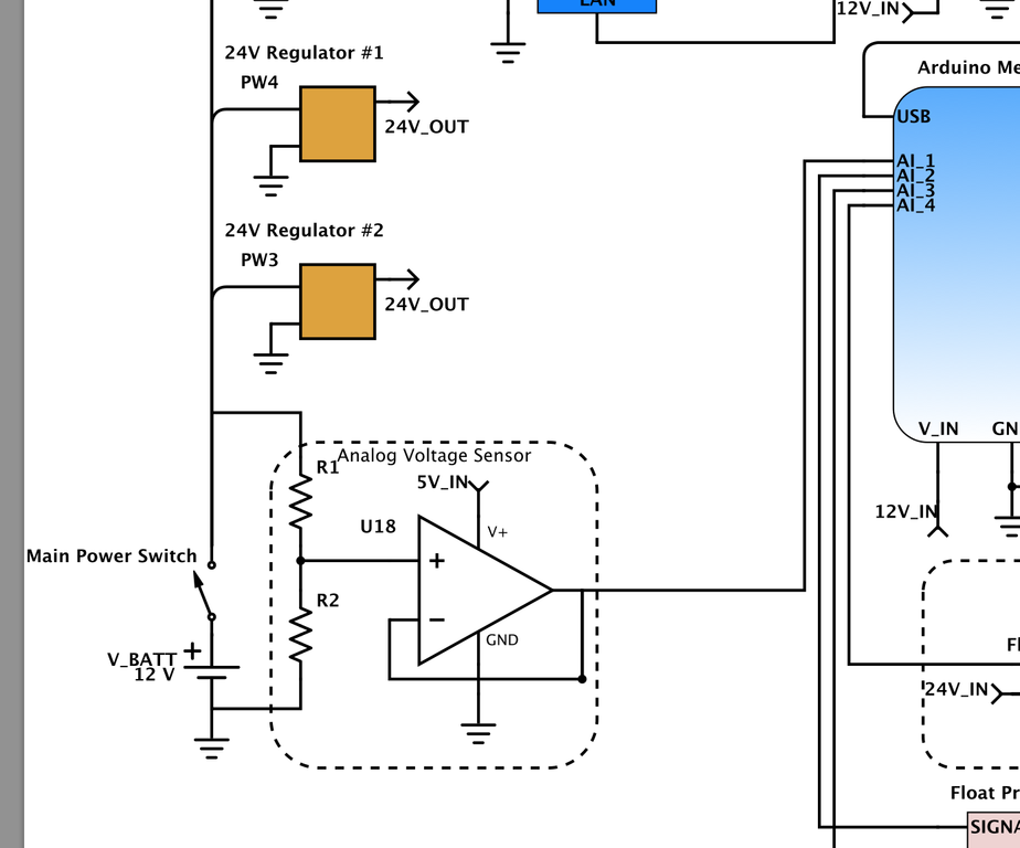
My idea is to have the voltage from the battery divided, so that high (~13v) would come out to be 5v, and low (10-11v) would come out to be lower. After the voltage is divided, a unity gain op-amp would be used to add current protection to the microcontroller.

Here's part of the schematic that I'm working on to give some visualization:

schematic

Would this be a good circuit for sensing battery voltage? Even if it is, could I make any improvements?

\$\endgroup\$
2
  • \$\begingroup\$ I don't think the op-amp in the context of current protection is relevant at all. Am I wrong here? The op amp in that circuit is implemented as a buffer and as such provides a low output impedance (~100 ohms or less) to the ADC's high input resistance. Another benefit of the device is that the ADC does not load the circuit and skew the actual voltage by sinking (excessive) current. \$\endgroup\$
    – sherrellbc
    Commented Jun 23, 2014 at 20:04
  • \$\begingroup\$ You're right; it's irrelevant, but the opamp's output impedance won't be anywhere near 100 ohms. It would be, operating open loop, but because of its huge open-loop gain being used almost entirely to provide feedback to the input, it'll be an almost ideal voltage source with its output resistance pretty close to zero ohms. \$\endgroup\$
    – EM Fields
    Commented Jun 24, 2014 at 12:23

2 Answers 2

3
\$\begingroup\$

Current limiting could be provided by the resistors themselves. If you made a 3:1 divider from a 10k and a 5k resistor, 15 volts on the input would translate to 5 volts on the output. Assuming the lower resistor (5k) went open circuit, the circuit would try to produce 15 volts but be limited to something like 1mA due the the Arduino's input schottky diodes and the 10k resistor.

Simpler is better but if you have a worry that the voltage could rise significantly higher than 15 volts then make the resistor divider a greater ratio. As regards the op-amp providing current limiting this is not really the case unless it is run from the same supply as the arduino. Another problem with the op-amp is that even a rail-to-rail device is not truly rail-to-rail and you might lose 50mV top and bottom.

My advice, work out the input voltage limits and keep it simple with a resistor divider and no op-amp. Add a 100nF across the 5k resistor and any glitches that may be on the battery supply will be largely killed-off by the cap.

Another point is that you can't make the resistors too large because the spec for the ADC on the arduino suggests 10k is the maximum input resistance to accurately measure a voltage source. This is significantly helped by the 100nF capacitor I mentioned.
\$\endgroup\$
4
  • \$\begingroup\$ I've never read of that 10k output resistance (of the circuit being measured) on an ADC before; why is this constraint imposed on the ADC input? Does it have to do with the ADC input resistance and the measured circuits output resistance forming some sort of a divider? \$\endgroup\$
    – sherrellbc
    Commented Jun 23, 2014 at 20:06
  • \$\begingroup\$ @sherrellbc because of the sample and hold capacitor and the multiplexer. \$\endgroup\$
    – Andy aka
    Commented Jun 23, 2014 at 21:31
  • \$\begingroup\$ @Andy: The OP asked for 5V out with 13V in, and for that he'd need a divider with 8K on top for 5K on the bottom. The problem with running that junction into the ADC circuitry is that the 5K will appear in parallel with the ADC stuff, changing the divider ratio and lowering the input voltage to the ADC, creating an error. Finally, with the divider output sitting at around 5V and a unity-gain buffer powered by 13V, there'd be no need for the opamp to have RR inputs or outputs, the input being well within the common-mode range of most opamps, and the output not even close to the rails. \$\endgroup\$
    – EM Fields
    Commented Jun 24, 2014 at 11:40
  • \$\begingroup\$ @emfields I know what was asked. My suggestion of 15 volt is to hint to him to be sure that 13 volts is the highest voltage. For an arduino I believe 10k is the highest recommended source impedance. \$\endgroup\$
    – Andy aka
    Commented Jun 24, 2014 at 13:28
1
\$\begingroup\$

Use a 1.6 : 1 voltage divider to get 5V from the 13V input and then buffer it with a unity-gain opamp to get a low output impedance to drive the next stage:

    +13
     |
     +---------+
     |         |
   [16k]       |
     |         |
     +--------|+\
     |        |  >-+-- 5V>
   [10k]   +--|-/  |
     |     |   |   |
     |     +---|---+
     +---------+
     |
    GND       
\$\endgroup\$

Your Answer

By clicking “Post Your Answer”, you agree to our terms of service and acknowledge you have read our privacy policy.

Not the answer you're looking for? Browse other questions tagged or ask your own question.