2
\$\begingroup\$

I'm using an existing keypad with 8 LEDs that source power. I was hoping to use and LED driver of sorts, but all of the ones I find only refer to sinking power. Is it possible to use these drivers to source current, and if so is there a way of understanding how to convert the sinking specifications to sourcing? The Vcc for my system is 3.3V and LEDs are 3.4V and 20mA

Was looking at this TI TLC5917 driver.

The LEDs on keypad are Lite-On LTST-C150TBKT.

The circuit is setup like
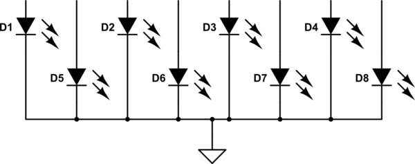
schematic

simulate this circuit – Schematic created using CircuitLab

\$\endgroup\$
3
  • \$\begingroup\$ Is that a ground connection on the top? It's confusing, because the symbol says ground, but usually it's turned the other way, and at the bottom of the schematic. An arrow up can refer to the positive power supply, but usually it's labeled "Vcc" or similar. \$\endgroup\$
    – Phil Frost
    Commented Aug 10, 2014 at 11:29
  • \$\begingroup\$ yes it's ground. fixed schematic. \$\endgroup\$
    – neufuture
    Commented Aug 10, 2014 at 11:53
  • \$\begingroup\$ @neufuture - how much current do you need intend to source to each LED? \$\endgroup\$
    – gbulmer
    Commented Aug 10, 2014 at 13:13

2 Answers 2

1
\$\begingroup\$

Firstly, these drivers do not sink or source power. The stuff they source or sink is current. Power is the rate of energy use or conversion. Current is the flow of electric charge. Very different things.

The arrangement of LEDs you have is called common cathode, because the cathodes of all the LEDs are connected to the same thing.

A driver designed to sink current can not be made to source current. It's certainly possible to design a driver to source current, but this would be a different component. I took a quick look on TI's web site and didn't find anything equivalent to the driver you were considering, but which sourced current. I'm sure someone makes one, but it's somewhat less common.

I'm guessing this is a hobby project, so you aren't going to incur any unacceptable cost by using a few more components. So, you might consider skipping the driver IC. Here's one way you might do it:

schematic

simulate this circuit – Schematic created using CircuitLab
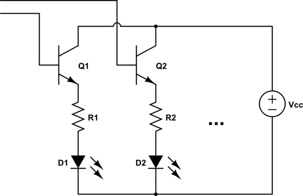
The transistor bases can run directly to a microcontroller, or an ordinary shift register.

\$\endgroup\$
3
  • \$\begingroup\$ This is how I had originally designed (with DMG1013UW diodes.com/datasheets/ds31861.pdf), but as the power source and forward voltage LEDs are both 3.3v I thought this may present an issue? \$\endgroup\$
    – neufuture
    Commented Aug 10, 2014 at 13:27
  • \$\begingroup\$ Rather, in this case what would be the recommended resistor values considering a steady 3.3V supply? \$\endgroup\$
    – neufuture
    Commented Aug 10, 2014 at 13:37
  • \$\begingroup\$ @neufuture That's a pretty important detail. Even your proposed LED driver wouldn't work, even if you had common-anode LEDs. Vcc needs to be at least the forward voltage, plus a little headroom for the regulator to work. You will need a higher voltage supply, or a boost converter. \$\endgroup\$
    – Phil Frost
    Commented Aug 10, 2014 at 21:10
0
\$\begingroup\$

At least one of the traditional 74-series families which will source over 10mA.
I typically use a 1K current limiting resistor on 5V (so under 5mA per LED), so 10mA is plenty to light an LED.

(Edit: 74 series families include 74F, 74AC, 74ACT, see for example TI "Non-Inverting Buffer/Driver"

Allegro make octal High-side drivers, for example the A2982, which is what you is asked.

I don't know if it is an obstacle, but that is in SOIC, which may be a bit awkward unless you have SMD facilities.

If SOIC is awkward, you may buy an 'adapter', a PCB which would carry a SOIC and give a DIP pin out. That is still a bit awkward to solder, however it makes things a more convenient, especially if you are using breadbard or stripboard (veroboard) to prototype or build something.

Otherwise you might use small P-MOSFETs. They will connect between each LED and +V. There will be a current limiting resistor. Again packages are mostly SMD.

\$\endgroup\$

Your Answer

By clicking “Post Your Answer”, you agree to our terms of service and acknowledge you have read our privacy policy.

Not the answer you're looking for? Browse other questions tagged or ask your own question.