3
\$\begingroup\$

enter image description here

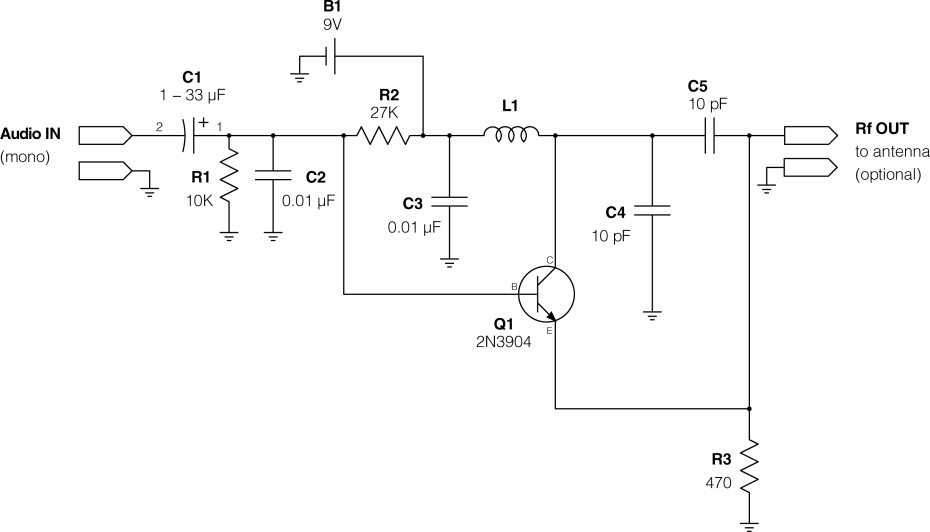
This is a circuit of crystal radio transmitter. I've tested it, and it works properly. but I can't understand everything in this circuit...

L1 and C5 make resonance frequency, Would you tell me if they are series or parallel and why ?

C1 , R1 and C2 for filtering the Audio (input). Am I right ?

What is the function of C4 ?

\$\endgroup\$
1
  • 1
    \$\begingroup\$ Um... technically not a "crystal radio", which is a receiver using an actual natural crystal and "cat whisker" as a detector stage. AM transmitter, though. \$\endgroup\$ Commented Aug 29, 2014 at 4:01

1 Answer 1

3
\$\begingroup\$

Actually, L1 and C4 are the resonant tank circuit for the oscillator. They are in parallel, because C3 effectively shorts the RF signal to ground. C5 provides the feedback to the transistor so that it oscillates.

\$\endgroup\$
2
  • \$\begingroup\$ Thanks, I was thinking C5 was just output coupling and was having trouble seeing the feedback path. \$\endgroup\$ Commented Aug 29, 2014 at 13:15
  • \$\begingroup\$ R1 and R2 set the DC level on the base of the transistor. C1 with R1 and R2 acts as a high pass filter, allowing audio in without affecting DC conditions. \$\endgroup\$ Commented Nov 16, 2014 at 2:26

Your Answer

By clicking “Post Your Answer”, you agree to our terms of service and acknowledge you have read our privacy policy.

Not the answer you're looking for? Browse other questions tagged or ask your own question.