0
\$\begingroup\$

I am working on a temperature measuring circuit using a pt100. The input of my instrumentation amplifier (AD8226) is between 80-200mV. The Gain is set to 20.84 so I get an output range of 1.7-4.2V. I want to shift down those voltages to 0-2.5V for my ADC.

I only have a precise 2.5V Voltage reference. Whats the best way to get -1.7V for the reference pin or is there a different way to shift the levels down so I can use the entire ADC voltage range?

\$\endgroup\$
5
  • \$\begingroup\$ It would go a long ways if you could specify just what amplifier you are using. This way it may be possible to suggest an efficient way to subtract out the net -1.7V that you need on the output. \$\endgroup\$ Commented Jan 8, 2015 at 16:40
  • \$\begingroup\$ I am using the AD8226 \$\endgroup\$ Commented Jan 8, 2015 at 16:42
  • \$\begingroup\$ @user1821517 Knowing more about your ADC would also help us answer your question. What model ADC are you going to use? If it's in a μC, then tell us the model of the μC. \$\endgroup\$ Commented Jan 8, 2015 at 19:36
  • \$\begingroup\$ I meant to write ADC8226 \$\endgroup\$ Commented Jan 8, 2015 at 21:37
  • \$\begingroup\$ @user1821517 I don't have any luck finding the datasheet for ADC8226. Are you sure that the part number is correct? Could you post a link to the datasheet? \$\endgroup\$ Commented Jan 9, 2015 at 0:40

3 Answers 3

1
\$\begingroup\$

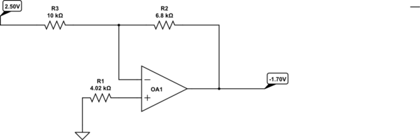
You can use an op-amp to generate -1.7V from the 2.50V reference. Most instrumentation amplifiers require a low impedance input for the reference input.

schematic

simulate this circuit – Schematic created using CircuitLab

If the op-amp has very low bias current you may not need R1. Of course the op-amp requires a negative supply for this to work.

\$\endgroup\$
5
  • \$\begingroup\$ I only have 3.3V to GND available. How would I get a negative voltage from an opamp without dual supply voltages? \$\endgroup\$ Commented Jan 8, 2015 at 16:24
  • \$\begingroup\$ You can generate the negative supply from the +3.3 using a charge pump (or a DC-DC but a charge pump would be more appropriate). The instrumentation amp will also need a negative supply. \$\endgroup\$ Commented Jan 8, 2015 at 16:25
  • \$\begingroup\$ My instrumentation amplifier works with a single supply. So I won't get around creating a negative voltage on my board? \$\endgroup\$ Commented Jan 8, 2015 at 16:29
  • \$\begingroup\$ You might be able to get around it, but that's not quite what you asked. You could use an op-amp to subtract a voltage from the output, or use differential input to the ADC if it is supported. \$\endgroup\$ Commented Jan 8, 2015 at 16:32
  • \$\begingroup\$ Dang single sided opamp circuits. Can you make +1.7 V, and run that through a differential opamp circuit. I think that should work single sided.. (but I could be wrong.) \$\endgroup\$ Commented Jan 8, 2015 at 17:32
1
\$\begingroup\$

Usually you can modify the input circuitry to the instrumentation amplifier to offset the output voltage.

If it's a three-wire RTD then there is usually a second current source to work with. The details depend on your arrangement- in the simplest case (two-wire RTD) you'd use a Wheatstone bridge arrangement with the resistor opposite the sensor determining the zero balance. There's little other reason to use an instrumentation amplifier anyway- a regular op-amp would do as well for a single-ended input.

\$\endgroup\$
1
  • 1
    \$\begingroup\$ I agree, he should post how he is currently hooking the RTD up. It may be a simple way to change how he has a biasing it. \$\endgroup\$
    – justing
    Commented Jan 11, 2015 at 3:41
0
\$\begingroup\$

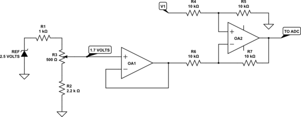
The simplest way to do what you want is to use a couple of op amps. Taking the output of the first amp as V1,

schematic

simulate this circuit – Schematic created using CircuitLab

will do the job. A few notes:

Use 1% resistors. They're cheap these days, and you don't have to worry as much about tolerances stacking up the wrong way.

OA1 is needed because as the input changes, so will the voltages at OA2s inputs, and this will affect the loading on the pot output if you don't have a buffer.

OA2, in particular, must be a rail-to-rail op amp that will operate at 3.3 volts. And even then, be aware that it won't go exactly to either 0 volts or 3.3 volts, but will be within 10 or 20 mV, depending on load.

\$\endgroup\$
2
  • \$\begingroup\$ Thanks for that circuit! Looks good. The reason why I wanted to use a instrumentation amp was because I heard that they do make a big difference in measurement applications(e.g. input resistance) I am trying to get the temperature measurement as accurate as I can \$\endgroup\$ Commented Jan 10, 2015 at 11:53
  • \$\begingroup\$ While what you say is true, it's not entirely relevant in this case. The pt100 only has a resistance of 100 ohms at 25C, so a measurement impedance of, say 100 k will only cause an error of 0.1%, and since you will probably be using 1% resistors at best, amplifier tolerances will hurt you much more than input impedance. And unless you have gotten sophisticated enough to produce a stable current source to drive the sensor, your measurement techniques may well do worse. I'd suggest you post your measurement circuit as another question and ask for a critique. \$\endgroup\$ Commented Jan 10, 2015 at 16:58

Your Answer

By clicking “Post Your Answer”, you agree to our terms of service and acknowledge you have read our privacy policy.

Not the answer you're looking for? Browse other questions tagged or ask your own question.