6
\$\begingroup\$

I've recently gotten the itch to build a POV Display. I'm wanting to build the sort that rotates "vertically" (like a fan or bicycle rim) and I'm finding very little information on how to actually do it. Can anyone find any resources for actually building it and what math is involved?

Also, is it possible to have the POV control circuitry located in an area that is not spinning and just have LEDs (and maybe LED drivers) actually spinning?

\$\endgroup\$
5
  • \$\begingroup\$ This is not difficult to find. There's even a kit adafruit.com/products/5 and website all about it ladyada.net/make/spokepov \$\endgroup\$
    – endolith
    Commented Aug 12, 2011 at 21:12
  • \$\begingroup\$ @Earlz I could email you a pretty detailed write up I did on a 3D POV display I made if you would like it. I never published it to the web anywhere though... \$\endgroup\$
    – NickHalden
    Commented Aug 12, 2011 at 23:32
  • \$\begingroup\$ @JGord Could you post it here or make a pastebin or something similar? \$\endgroup\$
    – Earlz
    Commented Aug 13, 2011 at 1:15
  • \$\begingroup\$ www.dropbox.com provides up to 2 GB of free storage for files that can be readily accessed by others. I'd bee keen to see details if available. \$\endgroup\$
    – Russell McMahon
    Commented Aug 13, 2011 at 13:08
  • \$\begingroup\$ Report and Video1 and Video2 \$\endgroup\$
    – NickHalden
    Commented Aug 17, 2011 at 23:17

3 Answers 3

7
\$\begingroup\$

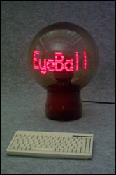
Search for "Propellor Clock" for many examples of this.

A number of sites with full construction implementation are listed below.
enter image description here

Theory:

Propellor clocks are "just a matter of engineering" - ie the principles are well understood, "you just have to do it". The gap between knowing how and doing can be large :-) - but following some of the examples below will make it easier.

Basic process

  • Desired display information is converted to a dot mapped display format.

  • A rotor is spun horizontally or vertically.

  • A line of display dots (usually LEDs) are arranged in a line.

  • Spin speed is known or calculated.

  • Starting position per rotation is determined (sensor of some sort usually)

  • Lines of dot data are output at a rate based on rotational speed and desired display length.

  • All the rest is "engineering" :-)

Getting power "across the gap" may be done with a motor winding used as a power pickup (Bob Blick), induction between two coils, solar panel, brushes and slip rings, separate alternator (perhaps with a bob-weight positioned "stator" **), or ...

Information transfer can be by having it on the rotor already (clock etc), short range RF, optical, contacts (less desirable), capacitive, ... .

For external feed of dot data per rotation (as asked about) an eg 10 x (5x7) dot display = 350 dots at say 30 Hz rate x say 1/3 of an arc illuminated the data transfer rate = 350 dots x 30 Hz x 3 ~= 32 kbps. A more complex dot mapped display may need data rates of up to about 100 kbps. Such rates are certainly achievable but potentially 'annoying' to implement. The low cost of microcontrollers means that even if most processing is done external to the rotor, data speed can be much reduced by only feeding a "frame buffer" (one display of information) as required. A second buffer could be built while the current one is displaying. It may be that an acceptable compromise would be partitioning the task so that the rotor processor had all display data and implemented effects such as scrolling, flashing etc while the remote processor looked after data acquisition and management.

EXAMPLES:

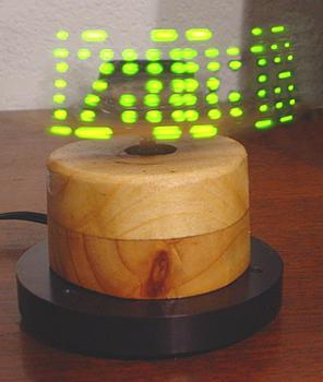
One of the best known DIY versions, for which full construction details are available is "Bob Blick's propellor Clock". This was based on earlier versions by other people and in turn many people have adapted Bob's design.
enter image description here

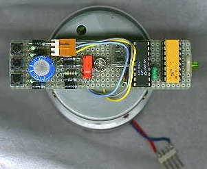
Full construction details are here of Bob Blick's Propellor Clock

Here is a propellor clock site with links to a number of other related sites and designs. Some examples -
enter image description here

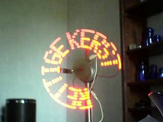
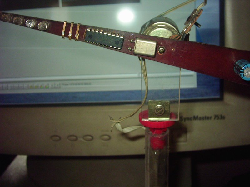
Another propellor clock - looks useful - Neelandans? propellor clock
enter image description here

Instructables on motor implementation. Note this comments on bob Blick's use of an extra coil for powering the electronics.

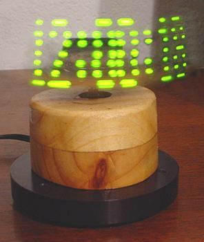
And again - horizontal orientation - another Bob Blick inspired design
enter image description here


132 LED driver IC !!!!

I just heard (October 2011) on PICList (thanks Colin) about this IC . 132 LED driver from Austrian Micro. Digikey sells a number of their ICs but do not list this one as yet.

They say:

  • The AS1130 is a compact LED driver for 132 single LEDs. The devices can be programmed via an I²C compatible interface.

    The AS1130 offers a 12x11 LED-Matrix with 1/11 cycle rate. The required lines to drive all 132 LEDs are reduced to 12 by using the cross-plexing feature optimizing space on the PCB.

    The whole LEDMatrix driving 132 LEDs can be analog dimmed from 1 to 30mA in 256 steps (8 bit). Additionally each of the 132 LEDs can be dimmed individually with 8-bit allowing 256 steps of linear dimming.

    To reduce CPU usage up to 36 frames can be stored with individual time delays between frames to play small animations automatically.

    The AS1130 operates from 2.7V to 5.5V and features a very low shutdown and operational current. The device offers a programmable IRQ pin. Via a register it can be set on what event (CP request, Interface timeout, Error-detection, POR, End of Frame or End of Movie) the IRO is triggered. Also hardware scroll Function is implemented in the AS1130.

    The device is available in a ultrasmall 20-pin WL-CSP and an easy to solder 28-pin SSOP package.

Product page / General details here

Data sheet here

http://www.austriamicrosystems.com/eng/led-driver/AS1130

\$\endgroup\$
5
\$\begingroup\$

I have done this before in a commercial product:

We also did a follow on version that was larger and had 96 full color pixels vertically.

The biggest problem with not putting the control circuitry on the rotating part is the bandwidth that is then required between the rotating and fixed parts. We put the per-pixel control on the rotating board, and sent higher level (and therefore lower bandwidth) information to it from the fixed part. In both units, we used a hollow veritical shaft with a IR LED on the fixed part and a detector on the rotary part to send the information.

\$\endgroup\$
4
  • \$\begingroup\$ If you look into slip ring commutators, you can actually get an 'infinite' number of communication lines between the stationary control and the rotating part. You sandwich comm lines with insulators. I'm not sure how many you could actually get and what speed you could operate at before capacitive coupling and such becomes a problem... but it would certainly be enough for a small LED matrix. It just increases the thickness of the spinning shaft. \$\endgroup\$
    – NickHalden
    Commented Aug 13, 2011 at 3:55
  • 1
    \$\begingroup\$ @JGord: Slip rings are not good for communication lines. They scrape and bounce, so there is a lot of noise on them. Slip rings can be OK for transferring power, since it's easy to provide enough capacitance to ride out short dropouts. Slip rings in general have problems of wear and friction though. \$\endgroup\$ Commented Aug 13, 2011 at 13:03
  • \$\begingroup\$ Definitely valid concerns and again it depends on your application. But because you can get so many of them I could imagine a system with sufficient ECC in order to eliminate problems with noise. Also, depending on the speed of your communication vs. rotational speed it might not even be an issue to begin with. The wear and friction I don't think you can do anything about... I tend to not worry about longevity of my solutions since I'm still a student and everything is for proof of concept. I should probably get out of that habit \$\endgroup\$
    – NickHalden
    Commented Aug 13, 2011 at 17:42
  • \$\begingroup\$ What about using slip-rings with AC-coupled differential signals? Do they behave nicely capacitively even when dirt interferes with passing DC? I know capacitive sensing used to be used in high-quality keyboards. \$\endgroup\$
    – supercat
    Commented Oct 7, 2011 at 15:15
4
\$\begingroup\$

I come for sure a little bit late in that topic but I think that you will enjoy what I have to propose.

Our 112 RGB LEDs (resolution of 224*224 pixels) is able to display whatever video file you want.

You can see the result of our work on this video.

To be able to do that we embedded a Gumstix(that is a tiny computer) on our blade: thank to that we were able to connect via wifi to the blade (yes the wifi signal is still received at 1000 rpm!) and so to send any information to the blade. Moreover this gumstix ran linux so launching any video is as easy as launching any video on your pc. The video flow is just sent to an FPGA which computes in real time, according to the angular position given by a rotary encoder, which LEDs to lighten or not.

Three of us, students from a french school, realized this project in less than three months. If you want to do the same, there much more information on our website.

\$\endgroup\$
1
  • 1
    \$\begingroup\$ So you had a gumstix and FPGA on the blade? \$\endgroup\$
    – Earlz
    Commented Oct 4, 2012 at 13:31

Your Answer

By clicking “Post Your Answer”, you agree to our terms of service and acknowledge you have read our privacy policy.

Not the answer you're looking for? Browse other questions tagged or ask your own question.