0
\$\begingroup\$

Im new to PCBs, know the basics of electronics and testing of individual components. I have a PCB (of an ATX supply) that is not working when I power it, so I thought of testing each components like resistors, transistors, diodes, capacitors etc.

Since all these components are in-circuit together, is it possible to test them with a multimeter without removing them from the PCB, as I am doubtful whether the other in-circuit components should affect the meter reading?

I could not find a direct answer on the net, that is why I ask here. My browsing ended up with partial answers that, first you need to desolder each component completely and test individually, or desolder all legs except one being back on board and then test them, wouldn't that a be a tedious process. I have read that the order best to be followed for PCB testing goes like visual inspection of blown or cracked components or broken PCB tracks, inspection for heated components when powered, replacing ICs and running the PCB for a check for faulty ICs.

I would like to know the correct order and how to test basic PCB components whether in-circuit or not, if in-circuit do I have to power up the PCB. Saw few costly devices are available for PCB troubleshooting on markets, can't we do this at home with our cheap multimeters?

Well while working with electronics I felt the need for a DC bench power supply, and that is when I found on the net to convert an ATX to DC power supply, so thought of repairing my old one. Therefore I to need to get the ATX power supply working first.

My real problem with the ATX supply having a 20 pin motherboard connector is that, when I connect it to the supply and jump PS_ON#(Green) and COM(Black) pins, the fan doesn`t turn nor I get a voltage reading across other pins (except a 5V reading across COM and 5VSB pins). How should I start to troubleshoot my device and make it working.

\$\endgroup\$
8
  • 3
    \$\begingroup\$ Whenever I see a block paragraph, I immediately stop reading. Use paragraphs, and separate them. It makes it easier to read, and if it's easier to read, more people will read it, and more people who know the answer can respond. \$\endgroup\$
    – efox29
    Commented Jun 18, 2015 at 10:24
  • 1
    \$\begingroup\$ Functional fault-finding is by far the best method to solve a non-working PCB (whether it is a new design or not). To help you, please provide a schematic so we can make pointers. \$\endgroup\$
    – Andy aka
    Commented Jun 18, 2015 at 10:26
  • \$\begingroup\$ After the schematic, what your circuit is supposed to do? Before individual checking there is a lot of measures that will help you. It's a bit like medicine, if you know the symptoms you may find the sickness and so, prescribe a recipe. Sometimes you may need further exams and sometimes you just try different (not totally random) procedures. Check for causes and consequences and you will optimize the time you will spend and also will sharp your skills. \$\endgroup\$ Commented Jun 18, 2015 at 10:46
  • \$\begingroup\$ Can you tell us more about the circuit board? Is it possible to describe the circuit beyond the resistors, capacitors and diodes \$\endgroup\$ Commented Jun 18, 2015 at 10:55
  • 1
    \$\begingroup\$ ATX power supplies are complex beasts. Just replace it. \$\endgroup\$ Commented Jun 23, 2015 at 2:07

4 Answers 4

4
\$\begingroup\$

The order and method to debug and root cause the failure depends on the individuals experience and skills. A multimeter is capable of assisting a root cause analysis process to a great extend, but depending on the complexity of the circuit you need other tools too.

I am assuming that you have the electrical schematic diagram, PCB Layout and part placement drawing for the circuit. For starter the following follow might work.

  1. Power up the PCB and check if the initial power supply stage is functioning and supplying the necessary power to the next stage.
  2. Provide the necessary signal inputs check if the inputs are received by the subsequent stage and processed
  3. Check to see which of the outputs are active

At this point you will have dig deeper, it is difficult to advise with much knowledge of the circuit.

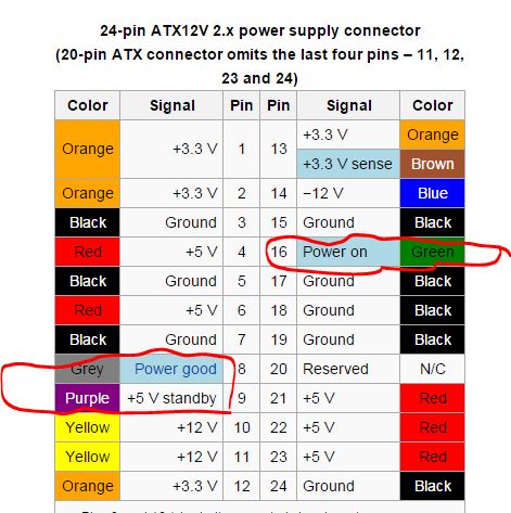
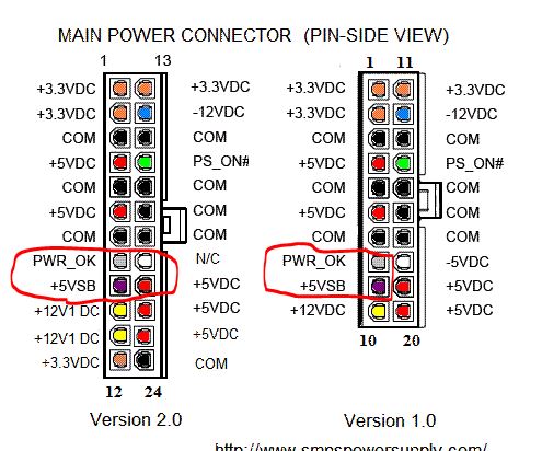
Edit: Now that we know that your circuit board is an ATX power supply the simplest debugging suggestion is to check if the 5VSB (Stand by supply) is active. With the multimeter check if you have 5V on this line. Below are to images to help you.

ATX power Supply -1 ATX power Supply -2

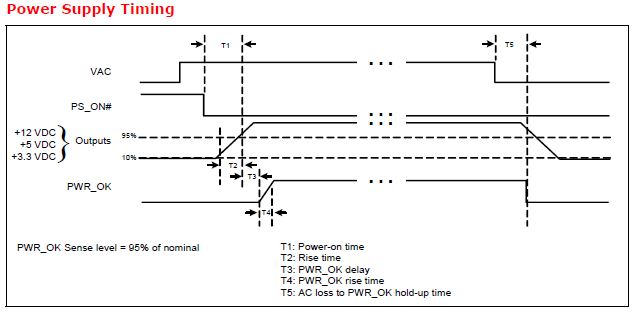
As far as I understand if you pull down the PS_ON (Green wire) the PWR_OK line will go high. This is a indication your power supply is good. Below is power supply timing sequence from Intel specification.

ATX power supply timing

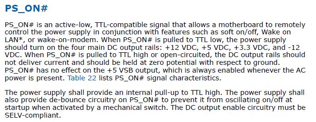
Also attach some notes about PS_ON and PWR_OK

PS_ON description PWR_OK description

Your may find the reference below helpful too.

Be Safe, Be careful, and Good Luck

References:

\$\endgroup\$
6
  • \$\begingroup\$ yes ensuring that supply reaches the parts is a very first thing to be made. the circuit is an ATX power supply. i did check for the initial part of receiving the supply, that works well. but i got stopped then, when capacitors and diodes takes the rest of the circuit. probably thats the place where i came up to the idea of testing components. because if they work well they carry supply forward isn`t the way \$\endgroup\$ Commented Jun 18, 2015 at 13:35
  • \$\begingroup\$ on your suggestion updated the question with certain add-ons that was necessary to highlight my main problem. Thought that repairing PCB involved a common method, but when many asked me for the schematic and the main fault, felt that i need to be more specific with the circuit and the problem, and now I understood that we cant repair PCB just like that. thanks as im new here \$\endgroup\$ Commented Jun 19, 2015 at 7:09
  • \$\begingroup\$ thanks for the guidance. Got a good start in troubleshooting and learnt well about ATX with your references. After reading your answer tried these out on my ATX, powered it up, got a 5V reading b/w POWER_GOOD and STAND_BY pins, then jumped PS_ON# with COM pins and at that time heard a "ticking" sound probably like the turning ON of a relay. Took readings across other pins but zero indication on my voltmeter. \$\endgroup\$ Commented Jun 20, 2015 at 14:21
  • \$\begingroup\$ Have one doubt regarding your above answer troubleshooting the PCB, two of the three things you mentioned were, firstly to check whether supply is reaching and its being passed on. Secondly to provide input signals to appropriate stages and check if they are processed correctly. So if the first thing i.e. supply is not passed on to a particular successive stage, and to find out whether is there any fault with that stage in not receiving supply and processing, do i have to power that stage with a required signal from a function generator or something and see if it processing?Is that the way \$\endgroup\$ Commented Jun 20, 2015 at 14:24
  • \$\begingroup\$ @FiazMR, Glad that the post has helped you. You have got passed the step 1 & 2. You are now at step 3. We will need more infomation about the power supply understand the failure. Details of Power supply, Model, schematic. If you opened up the power supply then pictures of the internal components. Bottom line is part of the output stage of the power supply is not fully functioning. Do little bit me research and post a separate question with all the details. BTW thank you for accepting the answer. \$\endgroup\$ Commented Jun 20, 2015 at 16:46
3
\$\begingroup\$

Random 'shotgun' replacement or testing of parts on a complex circuit board is about the worst possible way to do troubleshooting.

Frankly, you are far more likely to introduce more problems that will make the troubleshooting so difficult that it will be much cheaper to scrap the board than you are to stumble across the bad part(s) or bad connections.

The methods of troubleshooting at a board level vary a bit depending on whether the board ever worked or if it was a new board, but usually you start by visual inspection- looking for bad solder joints, fuses, smell test for smoked parts, bulged capacitors, BGA packages that may have gone intermittent, large power components and things mechanically connected to the outside world that may have been overstressed. If a fuse is bad do some preliminary tests to make the chance of blowing another fuse lower (check bridge rectifier and MOSFET/BJT switch resistance in-circuit).

Then apply power gingerly and begin functional testing with the power supplies- verify that they are within tolerance, then proceed to inject signals or manipulate inputs and observe the signal chain to the output.

There are a few parts that can be checked without removing them from the circuit (with power off and big capacitors discharged!)- not always to be sure that they are good, but to verify that they are bad. If a fuse measures substantial resistance or looks blown (not all can be seen). If a power transistor measures like a short both ways between CE/SD then it's probably blown (look at the schematic and see if there is anything across it that could explain the behavior). If a diode measures 600 ish one way and much higher the other way on a diode scale it's very likely okay. If a large cap measures a lowish resistance then goes up it's probably okay (but if it doesn't that doesn't mean it's necessarily bad).

Most failures in a previously working mass-produced board are related to mechanical or electrical stressed parts so a skilled technician will find his or her eyes drawn to those areas and may wiggle leads, use a microscope etc. and do testing to concentrate on those parts. For example, it is extremely rare for a small signal resistor or transistor that is not connected directly to an input or output to spontaneously fail. Cascade failures are not unusual, so if a resistor has burned up, something else probably failed too, or the user may have done something to cause the failure.

In a new one-off never-working board, about anything is possible, with bad joints and wrongly populated parts high on the list. It's also possible there is a design defect and not every instantiation of the design will work (because of marginal design). Generally the troubleshooting process is similar to the other situation, but now every part is pretty suspect.

In both cases, it is extremely difficult to effectively troubleshoot without a schematic (either a nice professional one or a mental model of what the circuit probably looks like) and a reasonably deep understanding of what is going on. It doesn't have to be enough knowledge to design the circuit, but enough to know that if part 'a' is shorted, what the consequences will be.

Other rules - bad semiconductors usually go shorted unless they are physically blown apart. Shorts are rarer than open joints. BGAs with lead-free are not very reliable. Aluminum capacitors and relays wear out. Fuses blow, but usually for a reason. Anything the user can put force on can damage the connections.

\$\endgroup\$
0
2
\$\begingroup\$

In my experience the most common issue is faulty electrolytic capacitors. They commonly bulge but not always. you can test them in-circuit just get an ESR meter and replace any you find with the same value and voltage but make sure they are good quality and low ESR units.

\$\endgroup\$
1
\$\begingroup\$

What if I told you that probably all the components on your PCB might be perfectly OK and that there is some other issue preventing your PCB to work.

What you have to do is troubleshoot. Understand how the circuit works and see where it does not do what you expect. Yes that is difficult. But there is one enormous advantage to it: you might learn something !!!!

But testing all the components is not going to give you the solution that you need.

Whether you can test a component in circuit with a multimeter depends on the circuit. Sometimes it's possible sometimes it's not.

If the costly device for testing PCBs is a continuity tester, then yes, you can do this with a multimeter. If it is a more advanced tester that can apply voltages etc, then no, you will need more equipment.

\$\endgroup\$

Not the answer you're looking for? Browse other questions tagged or ask your own question.