Im new to PCBs, know the basics of electronics and testing of individual components. I have a PCB (of an ATX supply) that is not working when I power it, so I thought of testing each components like resistors, transistors, diodes, capacitors etc.
Since all these components are in-circuit together, is it possible to test them with a multimeter without removing them from the PCB, as I am doubtful whether the other in-circuit components should affect the meter reading?
I could not find a direct answer on the net, that is why I ask here. My browsing ended up with partial answers that, first you need to desolder each component completely and test individually, or desolder all legs except one being back on board and then test them, wouldn't that a be a tedious process. I have read that the order best to be followed for PCB testing goes like visual inspection of blown or cracked components or broken PCB tracks, inspection for heated components when powered, replacing ICs and running the PCB for a check for faulty ICs.
I would like to know the correct order and how to test basic PCB components whether in-circuit or not, if in-circuit do I have to power up the PCB. Saw few costly devices are available for PCB troubleshooting on markets, can't we do this at home with our cheap multimeters?
Well while working with electronics I felt the need for a DC bench power supply, and that is when I found on the net to convert an ATX to DC power supply, so thought of repairing my old one. Therefore I to need to get the ATX power supply working first.
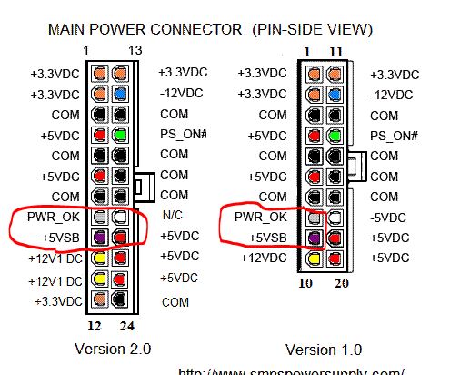
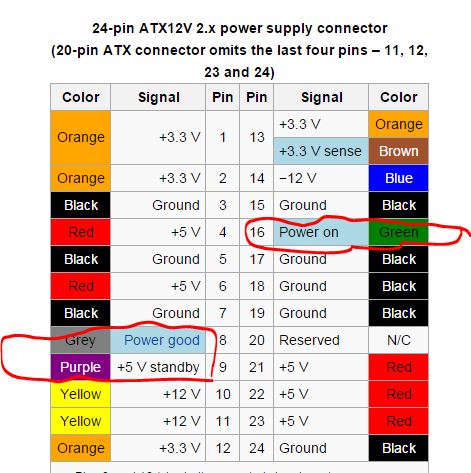
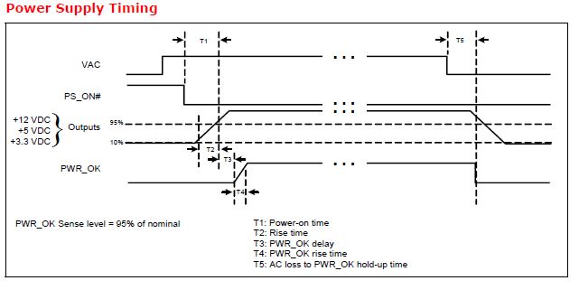
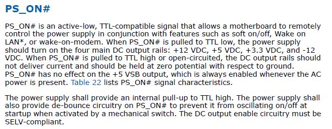
My real problem with the ATX supply having a 20 pin motherboard connector is that, when I connect it to the supply and jump PS_ON#(Green) and COM(Black) pins, the fan doesn`t turn nor I get a voltage reading across other pins (except a 5V reading across COM and 5VSB pins). How should I start to troubleshoot my device and make it working.


