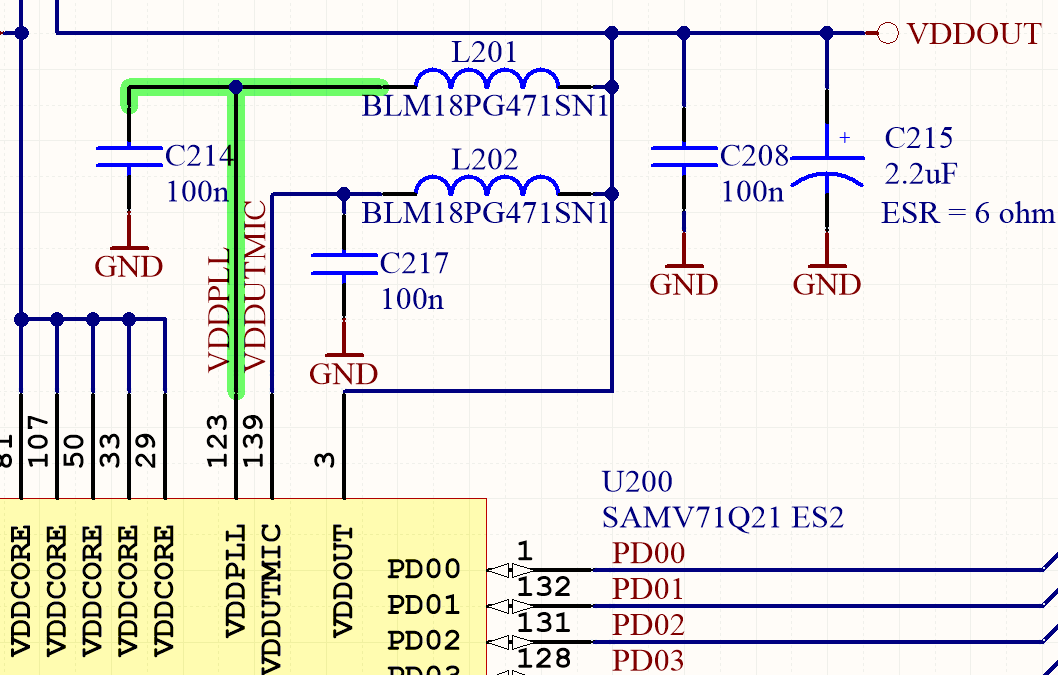
I have checked a reference design because I use the same microcontroller for my thesis.
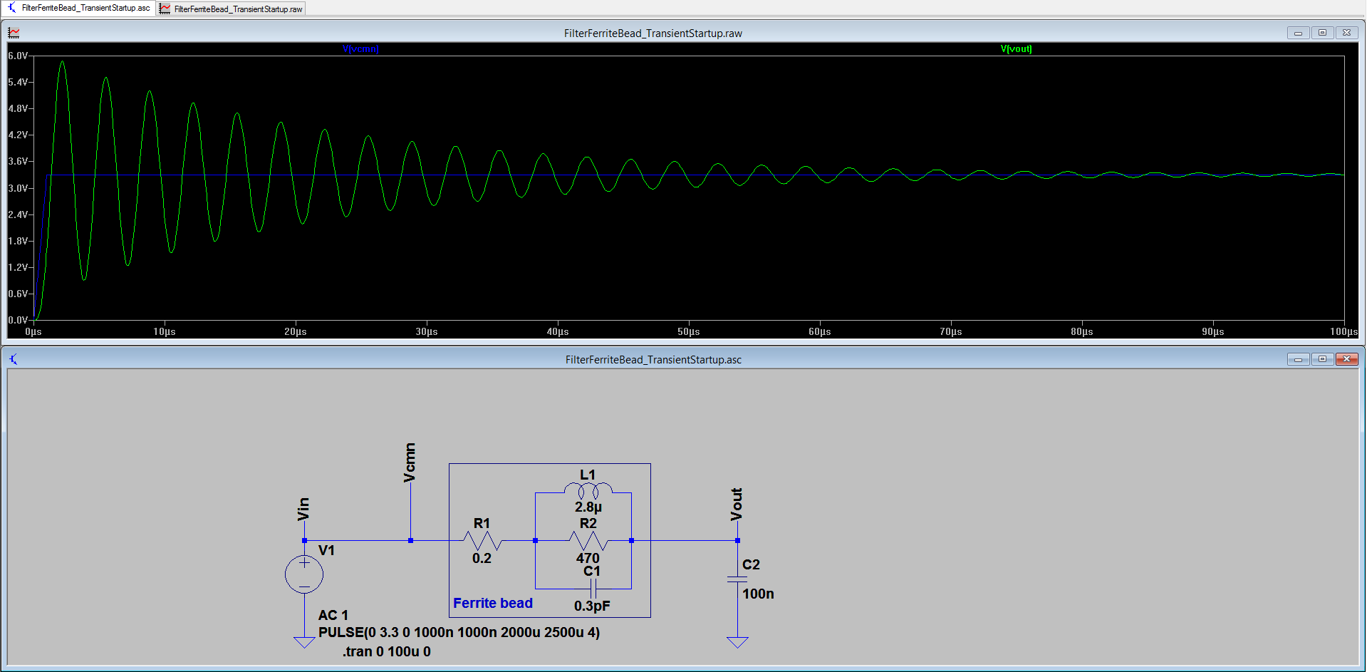
The PLL power input is filtered by a ferrite bead and a capacitor. I have simulated the circuit and I found that there is a strong resonance at 300kHz.
I assume the reference board is functional so I don't understand how this can't be a problem. Do you know why this is not a problem?

-
\$\begingroup\$ Reference boards are for a particular layout and stackup. A reference design is not guaranteed to work exactly as is, if you change anything from the original design. \$\endgroup\$– efox29Commented Sep 23, 2015 at 9:32
-
1\$\begingroup\$ And what is the problem exactly ? Is it your simulation or your real world measurements ? \$\endgroup\$– efox29Commented Sep 23, 2015 at 9:33
-
\$\begingroup\$ There are some documents which mentions these problems. The problem is a 3.3V rail is pushed by 6V voltage. Plus if there is any noise source on the board which causes some spikes on 300kHz then it is amplified on the resonance frequency. (so this filter is garbage on 300kHz) Actually it is worse on 300kHz than if it wouldn't there at all. \$\endgroup\$– QuentisCommented Sep 23, 2015 at 9:54
-
\$\begingroup\$ You feel that these documents which describe your problem are not worth posting for someone to answer your question, about why this is happening ? no ? \$\endgroup\$– efox29Commented Sep 23, 2015 at 9:56
-
1\$\begingroup\$ Your model of the ferrite is very crude. Additionally, does the voltage rail slew rate reflect reality? \$\endgroup\$– corecodeCommented Sep 23, 2015 at 10:01
1 Answer
Yes, resonance of capacitance and ferrite beads can be a problem. They're pretty high Q inductors at low frequencies, which can come as an unpleasant surprise if there is something floating around to ring them up.
You can try to improve things by increasing the capacitance to several uF so the series resistance adds damping or adding some parallel damping resistance, or a bigger ceramic cap + series resistor from VddPLL to ground.
You have assumed the PLL Vdd acts as a high impedance, which may be pessimistic, but I suspect not totally unreasonable.
-
1\$\begingroup\$ To prevent resonance of a bead having series resistance R and inductance L, R must be at least sqrt(4*L/C), where C is the capacitance on the side of the bead opposite the signal source. \$\endgroup\$– user4574Commented May 11, 2016 at 13:40
-
\$\begingroup\$ @user96037 Corresponding to a damping ratio of 1.0 (critical damping). See this \$\endgroup\$ Commented May 11, 2016 at 14:46
-

