0
\$\begingroup\$

I've picked up some IR sensors from a local electronics shop. The shopkeeper had no idea about the specification/part-no of the sensor. I've assumed it to be TSOP38238 as my sensor looks exactly like this.enter image description here
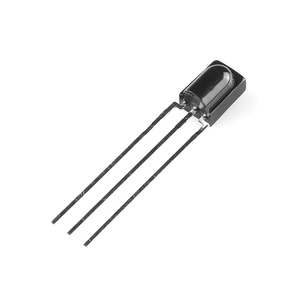
I am providing 3.3v (2A) to the sensor on the rightmost pin and have connected the center pin to the ground. I've used an household AC's IR remote to test it. The output is consistently 3.15-3.20v when no IR light is pointed to it. Strangely the output ranges between 2.7v to 3.00v when i point IR from my remote to it.

I want to hook this sensor to ESP8266 to an interrupt pin but i don't think the MCU will detect an interrupt (change) with such ouput.

\$\endgroup\$
5
  • \$\begingroup\$ How are you measuring the voltage? A DMM is too slow, you need a scope to see if you're getting proper pulses. \$\endgroup\$
    – user16324
    Commented Nov 15, 2015 at 15:15
  • \$\begingroup\$ I am measuring the voltage with a standard digital multi-meter .I don't have a oscilloscope. So should i try connecting the sensor to the MCU to see if i receive pulses properly ? Do you think this can be a issue of high current supply (2A) ? \$\endgroup\$ Commented Nov 15, 2015 at 15:23
  • 1
    \$\begingroup\$ If you don't have an oscilloscope then the MCU is your best bet. Don't use an interrupt pin because you will pick up noise. Instead poll a pin at double or triple the speed of the modulation instead. \$\endgroup\$
    – vini_i
    Commented Nov 15, 2015 at 15:26
  • \$\begingroup\$ @vini_i The MCU i am using doesn't have a hardware Analog input. So the software way is slow to read the pulses. What sort of noise will be introduced if i use the interrupt? Can it be avoided? \$\endgroup\$ Commented Nov 15, 2015 at 15:30
  • \$\begingroup\$ IR sensors pick up all kinds of noise, from the sun, from other IR sources, etc... This noise can commonly show up as random spikes in the wave form. To help reject that noise the IR stream is modulated. The modulation pulses the beam at a steady state. By sampling the wave form at a steady rate random spikes can be avoided. Be sure to sample at, at least, twice as fast as the signal. Also by sampling at a steady rate you have an easy time base to work with. If you use interrupts then you will pick up every spike and you have to create your own time base. \$\endgroup\$
    – vini_i
    Commented Nov 15, 2015 at 22:50

1 Answer 1

0
\$\begingroup\$

The output without incoming signal is high (logical 1) for these sensors. When you press a button on your remote, it actually switches between 1 and 0 quite fast (in ms, so not that fast,but still). That's why the RMS on your meter goes below 3 volts. If you have access to an oscilloscope, you could visualize an almost rectangular signal.

\$\endgroup\$
3
  • \$\begingroup\$ Thanks! Would there be a problem if i connect the output to the interrupt pin of my MCU? What can possibly introduce noise in this approach? \$\endgroup\$ Commented Nov 15, 2015 at 16:09
  • \$\begingroup\$ I'd follow the datasheet. Vishay's TSOP are excellent sensors and probably can be connected directly. However with other brands (Everlight, LFN), the datasheets recommend adding capacitors. Noise is caused by fluorescent lights as well as other factors, but the integrated circuit withing the sensor adjusts gain automatically to lower noise levels, so you should have no trouble. \$\endgroup\$
    – John Wick
    Commented Nov 15, 2015 at 16:29
  • \$\begingroup\$ I connected the sensors to my MCU and it gave accurate results with no noise. Those are indeed some great sensors. \$\endgroup\$ Commented Dec 8, 2015 at 17:23

Your Answer

By clicking “Post Your Answer”, you agree to our terms of service and acknowledge you have read our privacy policy.

Not the answer you're looking for? Browse other questions tagged or ask your own question.