2
\$\begingroup\$

I'm working on a Fisher Digital Vortex Mixer that has an intermittent issue in which the AC motor is energized, but no movement occurs. By rough estimate, this will occur on one of every 8 attempts.

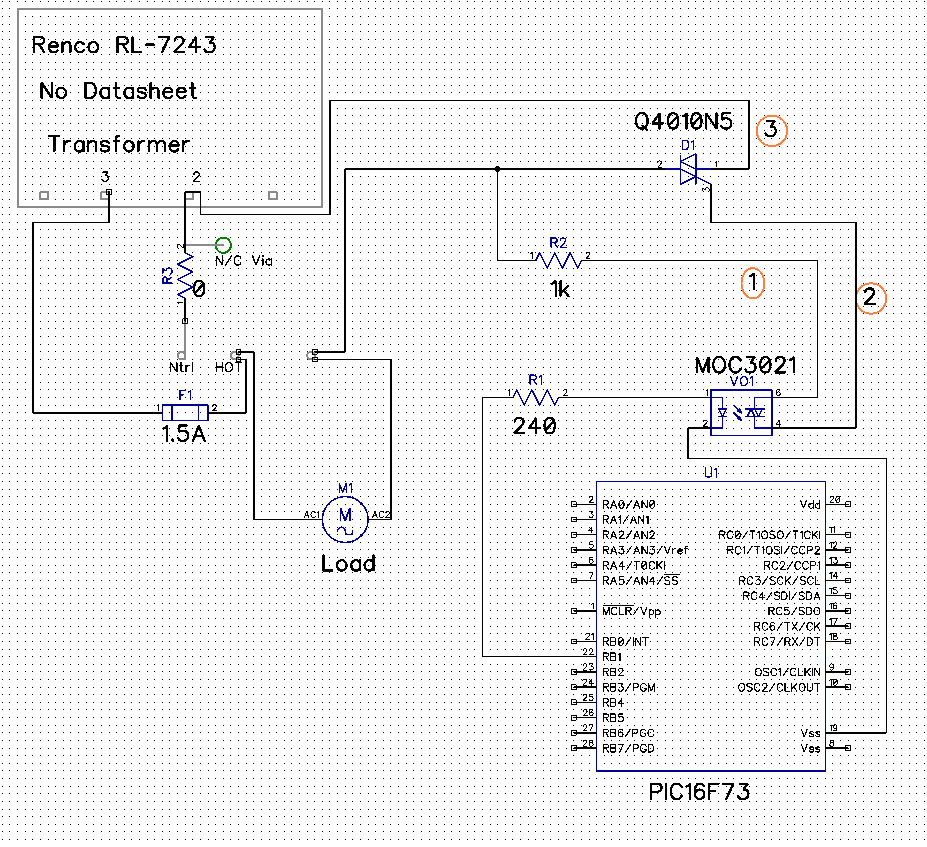
The circuit consists of a PIC16F73 that serves to activate a MOC3021 optocoupler that passes an AC signal to a Q4010N5 Triac. I have no access to circuit diagrams from the manufacturer, so this is my best analysis of the circuit:

Circuit based on visual/circuit tracing

As you can see, there does not appear to be any stubbing present, despite this system having an inductive load. It is certainly possible that I missed the stubbing circuit during my analysis, but having thoroughly examined the circuit over several days, I am relatively confident that it is not present.

The signal coming from the PIC microcontroller is a clean digital signal that seems to drive the optocoupler without issue.

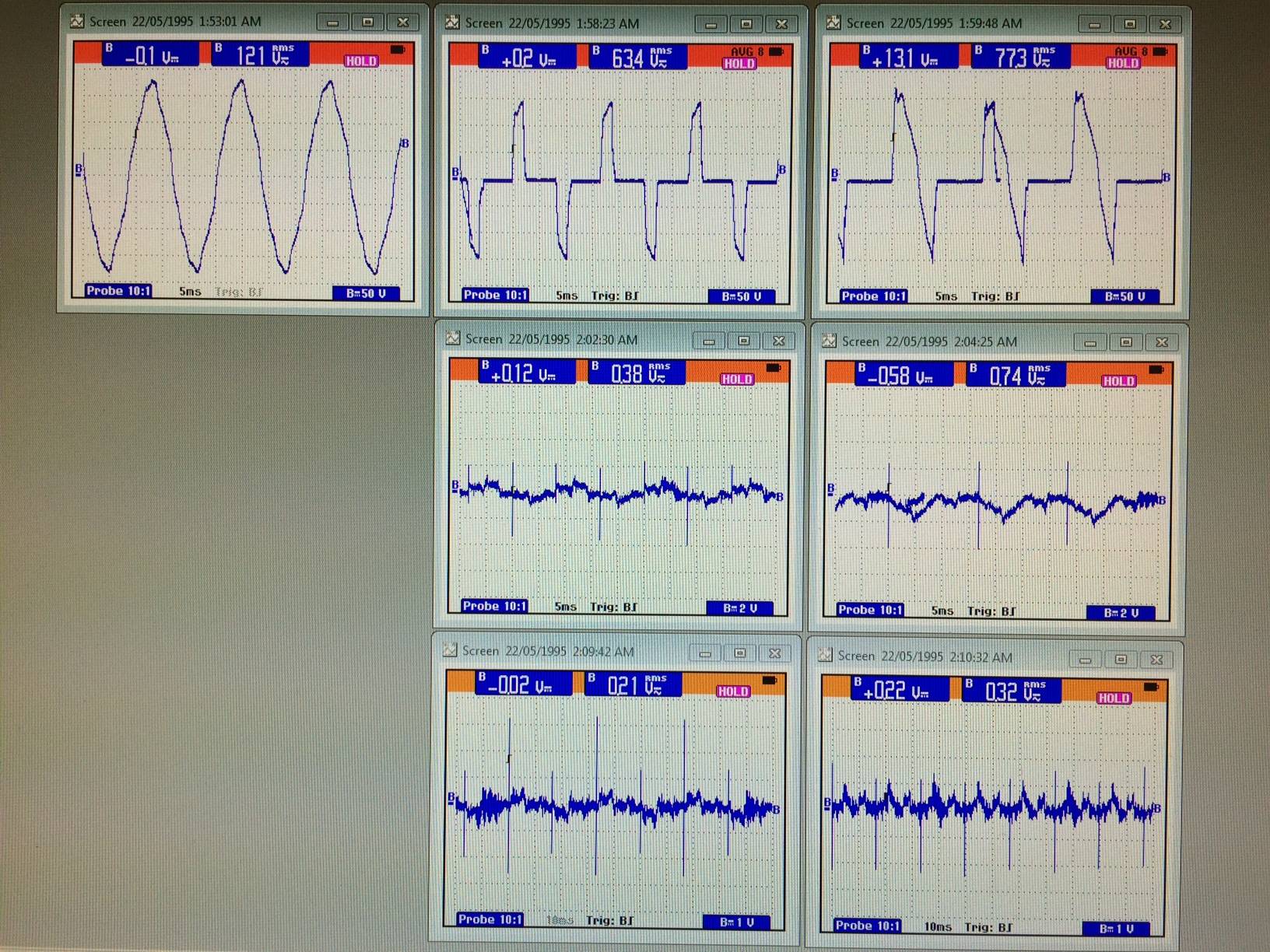
The signals going through the circuit at points 1, 2, and 3 (Circled in orange) are visible below.

Flukeview Images

The first row (point 1) depicts the No Button Press, the Good, and the Bad waveforms, in that order. The second (point 2) and third (point 3) rows only depict Good, then Bad waveforms.

Early in the analysis, someone else working on this circuit had replaced the Triac and Optocoupler as they were the likely suspects. There has been no change in behaviour after the replacements.

Despite my best efforts to figure out the cause of the waveforms I've witnessed in this circuit, I have not been able to find it. If you can offer any advice on how you would proceed, or if you require any additional information I haven't provided, please let me know.

Edited to remove extraneous pleasantries.

\$\endgroup\$
7
  • \$\begingroup\$ Normally repair questions do get shut down, but you seem to have dug into the details. SO thus might survive. But do remove the unnecessary greetings and "thanks you", they can interfer with the smooth working of the site. \$\endgroup\$ Commented Jun 7, 2016 at 21:31
  • \$\begingroup\$ A good first post. +1. You need to clarify the "between" points for measurements 1, 2 and 3. i.e., What was the reference. My initial thought was that there is no pull-down resistor between triac pins 1 & 3 but the datasheet examples don't have them either. Turn off the grid if you're redoing the screen shot. \$\endgroup\$
    – Transistor
    Commented Jun 7, 2016 at 21:41
  • \$\begingroup\$ Pleasantries removed as per your advice. \$\endgroup\$
    – Cothor
    Commented Jun 7, 2016 at 21:58
  • \$\begingroup\$ The reference I used was ground for all three measurements. I will remove grids for future screenshots of circuit diagrams. I appreciate the feedback. \$\endgroup\$
    – Cothor
    Commented Jun 7, 2016 at 22:01
  • \$\begingroup\$ There's no ground reference on your diagram and the transformer isolates the circuit from the mains neutral which (usually) is grounded. (1) Can you confirm that the transformer is isolating type. (2) Confirm that you mean ground as in "Earth" or "neutral". (3) If it is Earth, can you explain how you are getting stable readings between ground and an isolated circuit? -|-|- BTW, the problem with greetings at the top of posts is that they take up two lines of the summary on the main page. There is software to remove them automatically but yours must have been fiendishly clever. \$\endgroup\$
    – Transistor
    Commented Jun 7, 2016 at 22:26

2 Answers 2

2
\$\begingroup\$

I think you need to increase the igt of triac reducing R2 from 1K to 220 or 100 ohms, in addition optocouplers with inductive loads requires more input current to work properly; if you have the oportunity to change optocoupler I recommend to use the best optocoupler IL420.

\$\endgroup\$
3
  • \$\begingroup\$ I will give the resistor change a try first, then look into changing the optocoupler for a different model. What properties of the IL420 make you consider it to be the best optocoupler? \$\endgroup\$
    – Cothor
    Commented Jun 8, 2016 at 15:12
  • \$\begingroup\$ With inductive loads optocouplers require more input current from microcontroller, IL420 only need 2mA, if you not provided enough input current the coupler will turn on partially, also dv/dt its about 10kV/us. It's the only one optocoupler that internally have two back to back SCR's instead of triac as output. \$\endgroup\$
    – ise5755
    Commented Jun 9, 2016 at 20:59
  • \$\begingroup\$ The IL420 sounds like a solid optocoupler for this use. We did switch from the MOC3021 to the MOC3010 as the 3021 was designed for 220V applications. The PIC Microcontroller used will sink/source up to 25mA from the IO pins, while the MOC3010 only requires 10mA to turn on. The switching seems to be happening, based on the similar waveforms I'm getting on good and failed tests. Also, we calculated and used a 180 ohm resistor for R2, which made no change to the results. \$\endgroup\$
    – Cothor
    Commented Jun 10, 2016 at 15:04
0
\$\begingroup\$

If this is a universal motor, I would suspect a problem with the commutator or brushes. If you can give it a push when it fails to start when energized, and you find that it starts, you have a commutator/brush problem.

\$\endgroup\$
1
  • \$\begingroup\$ I have confirmed that the motor is a shaded-pole induction motor. \$\endgroup\$
    – Cothor
    Commented Jun 8, 2016 at 15:05

Your Answer

By clicking “Post Your Answer”, you agree to our terms of service and acknowledge you have read our privacy policy.

Not the answer you're looking for? Browse other questions tagged or ask your own question.