58
\$\begingroup\$

What I understood from the definition of current sources is that it is a source which supplies a constant current across a load no matter how the other parameters (like resistances for example) in the circuit are changed. Am I right?

If I'm right, what is an example of a current source used in a practical circuit?

Wikipedia gave the example of a Van de Graaff generator as a constant current source. (I didn't read the article, because there was a note that the section appeared to contradict itself. I didn't want to get confused.)

I can think of voltage sources - for example a battery which has a constant potential difference across its ends irrespective of the changes in the circuit it is connected to, but I cannot think of a current source. Any example I can think of involves change in the current when the resistances are changed.

\$\endgroup\$
2
  • 1
    \$\begingroup\$ Inductor is an example of a (variable) current source. It will keep pushing current though the circuit until it exhausts its energy. \$\endgroup\$
    – avakar
    Commented Mar 22, 2012 at 15:55
  • 1
    \$\begingroup\$ to clarify @avakar's comment - over very short time intervals, inductors look like current sources, but over the long haul, they run out of steam quickly. \$\endgroup\$
    – JustJeff
    Commented Mar 22, 2012 at 16:07

7 Answers 7

44
\$\begingroup\$

A current source is the dual of a voltage source. An ideal voltage source has zero output impedance, so that the voltage doesn't drop under load. It shouldn't be shorted, because in theory there would flow an infinite current.
An ideal current source has infinite output impedance. This means that the load's impedance is negligible and won't influence the current flowing. Like voltage sources shouldn't be shorted, current sources shouldn't be left open. An open current source will still try to source the set current, and the theoretical current source will go to infinite voltage.

edit (following your comment)
Here you can read impedance as resistance. If the current source would have a limited resistance changes in load would change the current, because the total resistance would change. You don't want that. So if the current source's resistance is infinite the load can be ignored and the resistance always remains the same (infinite). Therefore the current will as well.

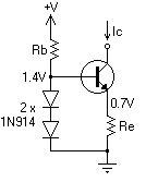
A practical current source may be constructed as follows:

enter image description here
One diode has the same voltage drop as the base-emitter junction, so the other diode sets the transistor's emitter to about 0.7V. A fixed voltage across a fixed resistor gives a fixed emitter current, which is about the same as the collector current if the transistor's \$H_{FE}\$ is high enough. (Strictly speaking this is a current sink rather than a current source, but the principle remains the same.)

Another current sink uses an opamp as control element:
enter image description here
The main thing you need to know about opamps in this configuration is that they will try to keep the voltage on both inputs equal. So suppose you set \$V_{SET}\$ to 1V, then the opamp will try to make the - input also 1V. It does so by inserting current into the transistor's base. This will cause a current through the load \$I_{LOAD}\$ which is (almost) equal to \$I_{SET}\$. And \$I_{SET}\$ is constant to get the 1V across \$R_{SET}\$, according to Ohm's Law:

\$ I_{SET} = \dfrac{V_{SET}}{R_{SET}} \$

Since \$V_{SET}\$ and \$R_{SET}\$ are constant, so will \$I_{SET}\$ be. QED.

\$\endgroup\$
4
  • 4
    \$\begingroup\$ I'm really sorry but I didn't understand anything you said. I don't know what impedance is. Can you dumb it down? How would you explain this to a high school student who has just been introduced to Ohm's law? \$\endgroup\$
    – Green Noob
    Commented Mar 22, 2012 at 15:34
  • \$\begingroup\$ @GreenNoob - I'll edit my answer. \$\endgroup\$
    – stevenvh
    Commented Mar 22, 2012 at 15:36
  • 2
    \$\begingroup\$ @GreenNoob, electrical Impedance (Z) = resistance x reactance. Impedance is how much the circuit will "impede" oppose changes to the current flow. In a DC circuit, there may be no reactance, and you can assume impedance means resistance. My comment is short, feel free to research it or view related questions on here :) \$\endgroup\$
    – Transient
    Commented Mar 22, 2012 at 20:51
  • 2
    \$\begingroup\$ @Transient Just to avoid confusion, \$Z = R + jX\$, where \$R\$ is resistance and \$X\$ is reactance. \$\endgroup\$
    – sblair
    Commented Mar 27, 2012 at 20:24
21
\$\begingroup\$

After reading your comments, I'm going to make a bit different answer to this question.

What exactly is a current source? It's nothing, or to put it a bit better it's just a mathematical model. The one you're describing does not exist, just as a voltage source doesn't exist.

I think that the main problem here is cased by this statement: for example a battery which has a constant potential difference across its ends irrespective of the changes in the circuit it is connected to which is incorrect. That it the behavior of ideal battery which is real as ideal current source and just like ideal current source it doesn't exist. The output (and internal state) of every real battery is affected by the circuit it is connected to.

So why do we have voltage and current sources? Well the idea is that engineer's job is to basically construct a device which does something pretty well and as it turns out for that complete understanding of how each component used in the device isn't needed. That is why we have things such as ideal current and voltage sources.

Let's get back to the battery example once again. Here's a simple experiment I did with a lithium polymer battery I have: First I completely charged the battery. Since it's a two cell battery, its voltage was 8.4 V when fully charged, even though its nominal voltage is 7.4 V. Then I connected a \$ 100 \mbox{ } k\Omega\$ resistor to the battery. It's voltage remained 8.4 V and from that I could perhaps conclude that the battery is indeed ideal voltage source since I connected the load to it, but its voltage did not change. Then I took an electrical motor I have and connected it to the battery and measured battery's voltage again. This time, it was 8.2 V. Clearly the motor affected the battery and it is no longer an ideal voltage source, even though it's the same battery as before. So I disconnected the motor and connected the resistor again and again the voltage at the battery was 8.4 V.

So what's happening here? Is the battery an ideal voltage source or not? Well we know it isn't because cause I said so at the beginning of the answer, but here I'll explain why it sometimes seems that it is and sometimes it seems that it isn't. As I said, the voltage source is a mathematical model. When the external circuit doesn't make a big impact on the operation of the battery, I can use it an when the external circuit does make a big impact on the battery, I can't use it. So we're using a simple model to represent behavior of a real circuit. Another model would be to use an ideal voltage source with a resistor in series at its output. When I connect and external load to that circuit, some voltage will be dropped at the internal resistor and the external resistor will see lower voltage at the output. This allows me to once again use the ideal voltage source to represent the battery and since I'm using the internal resistor together with the ideal voltage source, the output will more closely represent the behavior of a real battery. Should I want more precision, I could decide to use a more complex model and get more accurate results.

An important point of electrical engineering is to learn when to use right model to represent an extremely complex real-life circuit component (and even the humble resistor, when analyzed in detail, is a masterpiece of modern science). But to be able to do that, we start with simple circuits so that we can get to know how the simplest mathematical models actually work.

When we start analyses of more complicated circuit components, like transistor or diode for example, we'll break them down into a simple circuit consisting of things such as resistors and ideal current and voltage sources. This will allow us to simplify the behavior of more complex component and avoid analyzing in detail how it works, if the simple model is sufficient for our needs.

Completely same story works for current sources, but I decided not to tell it here since, as you can see from the other answers, circuits which can be modeled as ideal current sources are too complicated for you to understand at this point.

So to sum this up: There are no real-life objects that can be used to represent ideal voltage and current sources, but there are some objects that can be (in some cases quite closely) represented with ideal voltage and current sources. The best thing you can do now is to memorize correctly the definitions of ideal voltage and current sources and not to confuse them with real objects. This way you won't be surprised if a battery doesn't provide its nominal voltage or if a circuit labeled ideal current source starts smoking at one point although it should be completely immune to external changes in the circuit.

As a side-note consider what happens to ideal voltage source when its outputs are shorted and what happens to ideal current source when its outputs are open? And what happens when you short a battery an why all batteries have the warning not to short the output pins?

\$\endgroup\$
1
  • 6
    \$\begingroup\$ +1 Thanks a lot for answering. I really like your answers. They make many things a lot clearer for beginners like me :) \$\endgroup\$
    – Green Noob
    Commented Mar 23, 2012 at 7:19
8
\$\begingroup\$

Perhaps this answer will help. I'm saying pretty much the same thing as AndrejaKo, but my post will be shorter.

Much like voltage sources, current sources are only a theoretical construct. A battery can be a resonably close approximation to a voltage source, but it is not exact.

Howeer unlike voltage sources, which are approximated by batteries, there is no simple component that approximates a general current source particulkarly well. That does not mean the concept is not useful though, as many real world circuits can be modeled using the concept.

I've seen lab power supplies that have two knobs, one which adjusts voltage, the other adjusts current. To use these supplies as a voltage source, you simply set the current to the maximum, and dial in the voltage you want. As long as the circuit does not require more than the maximum current, the supply will supply your chosen voltage. To use it as a current source, dial the voltage to maximum, and set your desired current. The supply will provide that current as long doing so does not require a voltage greater than the maximum.

\$\endgroup\$
7
  • \$\begingroup\$ There are single component current sources, too! \$\endgroup\$ Commented Mar 22, 2012 at 18:10
  • \$\begingroup\$ To the best of my knowlegde there are none that don't require external compontents like a voltage source, and which are not logically compond components (like a battery+jfet combination). \$\endgroup\$ Commented Mar 22, 2012 at 18:29
  • \$\begingroup\$ @FedericoRusso Can you mention few single component current sources you know? \$\endgroup\$
    – Green Noob
    Commented Mar 23, 2012 at 7:21
  • \$\begingroup\$ @GreenNoob - Sorry, no. I'm trying to remember the part number of a 100\$\mu\$A device which I saw in the past, it looked like a diode and had a part number like (*)100. \$\endgroup\$ Commented Mar 23, 2012 at 10:51
  • 1
    \$\begingroup\$ The output of an alternator depends pretty heavilly on what is driving it. If the driving source is constant torque, then an alternator would indeed approximate a current source. If it were constant rotational velocity then it would resemble a voltage source. As I understand it, in practice the sources of most alternators are neither, providing constant power, with torque and rotational velocity varying depending on the load. \$\endgroup\$ Commented Mar 23, 2012 at 14:25
8
\$\begingroup\$

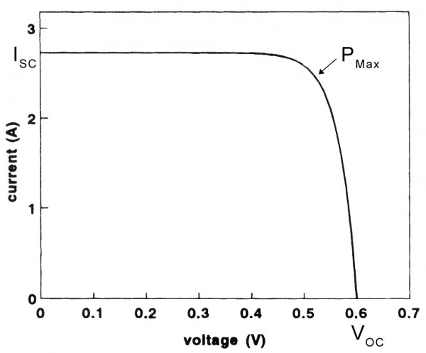
Solar panels act as a current source in part of their operating region. Look at this characteristics:

iv curve of a pv panel, source: www.itacanet.org

If you connect a 36mΩ resistor to the panel 2.75A will flow through the resistor yielding a 0.1V voltage drop on it. If you now increase the resistor to 150mΩ the current will remain constant at 2.75A and the voltage drop across the resistor will increase to ~0.4V.

If you keep increasing the resistance the current will eventually drop. This is because it is not an ideal current source. It act as one only in 0–0.4V range.

\$\endgroup\$
2
  • \$\begingroup\$ i think this is an important and helpful point. Some answers dwell on the concept of an ideal current source, but i think that creates confusion for a beginner. Discussion of an ideal source is unnecessary for initial understanding of the basic function of a current source. The OP didn't ask about "ideal" sources. It's sufficient to say "in the practical world, a device can supply a constant current within a limited range. But real circuits only require a limited range of constant current." Real-world circuits don't require an ideal current source. \$\endgroup\$
    – johny why
    Commented Jun 9, 2022 at 14:44
  • \$\begingroup\$ Great, simple answer. The OP mentions "other parameters (like resistances for example)". Your answer clarifies that it's specifically voltage, not "other parameters". And you include the all-important visual aid. \$\endgroup\$
    – johny why
    Commented Jun 9, 2022 at 14:47
6
\$\begingroup\$

If this helps you understand:

A current source is a bit like a battery which would adjust its own voltage to ensure the current flowing through it is the value you choose.

For example, if you have a 1A current source and you connect a 10 ohm resistor across it, the source will adjust its output voltage to 10 volts, which ensures 1 Amp runs through the resistor.

This is like saying that a voltage source will provide whatever current is necessary to ensure its voltage stays constant.

Thus, a current source will provide whatever voltage is necessary to ensure its current stays constant.

This is an oversimplified explanation, but I feel it gets the point through.

\$\endgroup\$
3
\$\begingroup\$

A current source is a circuit that has an ideally infinite output resistance; as you said, it gives (if possible) the same current no matter what it's connected to.

The concept is really easy: if you put it in a branch of a circuit, you will know that the current there will be that one; but, you can't know the voltage over that source unless deriving it calculating the drop over the other components.

Look at this simulation to understand better the concept. Turn on and off the switches and see the current flowing out from the source.

A current source can be made with a current mirror, where two BJT transistors are biased with the same base-emitter voltage to give the same (well, almost, the difference is two base currents) collector current. Then, one leg of the mirror is biased with a fixed load (often a resistor) to set the current, and then the other will replicate it.

This scheme can be improved with cascode connection (using common base transistors to increase output resistance) or other tricks, often using feedback.

Current sources are widely used in Op-Amps, where the gain stages have to be biased with accurate currents to provide balanced and higher gain.

\$\endgroup\$
7
  • 1
    \$\begingroup\$ Is this the current source that textbooks mean when they say - "Consider a current source in series with etc etc"? They introduce current sources very early in the text without clearly explaining how a practical one is constructed. A beginner will have no idea how a transistor or Op-Amp work. Can you clarify? \$\endgroup\$
    – Green Noob
    Commented Mar 22, 2012 at 15:41
  • 3
    \$\begingroup\$ A current mirror in itself is not a current source; the current in one leg depends on the current in the other leg. If that's not constant you don't have a constant current source. \$\endgroup\$
    – stevenvh
    Commented Mar 22, 2012 at 15:43
  • \$\begingroup\$ @stevenvh Right, I was about to write about biasing, then I forgot :) \$\endgroup\$
    – clabacchio
    Commented Mar 22, 2012 at 15:50
  • \$\begingroup\$ @stevenvh Then why have two legs? If the constancy depends on the first leg, then why not just use the first leg as your current source? What does the second leg give you that you don't get with the first leg alone? \$\endgroup\$
    – johny why
    Commented Jun 9, 2022 at 15:33
  • 1
    \$\begingroup\$ @johnywhy of course it's not ideal, but the concept is that, on one leg, you have a fixed load, such as a resistor. That creates a stable and arbitrary current on the collector of the transistor; this current is mirrored on the other leg at least approximately independent on the load. \$\endgroup\$
    – clabacchio
    Commented Jun 23, 2022 at 13:30
2
\$\begingroup\$

There are linear and switched power sources that can act as current sources. One method will be by taking a voltage source and regulating it's voltage to "compensate" for over-currents using feedback. that is called current mode.

There are however some converters that naturally act as current sources, having the theoretical name of Gyrators. these are voltage dependent current sources.

A related article to such sources (My article): http://www.ee.bgu.ac.il/~cervera/publications/pdf/conf4.pdf

\$\endgroup\$
0

Not the answer you're looking for? Browse other questions tagged or ask your own question.